2. SpaceStudio User Guide#
2.1. SpaceStudio IDE#
SpaceStudio is a tool designed for system designers that focuses on application acceleration and architecture evaluation. It offers extensive automatic code generation processes (for virtual platforms, drivers, communication layers, bootloaders, etc.) to avoid error-prone and time-consuming manual coding. SpaceStudio also provides means to evaluate and predict system performance using a non-intrusive monitoring infrastructure. Moreover, the architectures designed in SpaceStudio can be easily exported for downstream implementation.
2.1.1. Launching SpaceStudio#
After running the installer (please refer to the installation documentation), a “SpaceStudio” shortcut will be added to the Windows start menu/Ubuntu applications menu. Use it to launch the IDE.
2.1.2. Welcome Page#
When SpaceStudio starts, the welcome page below is shown. It displays quick access to create or open projects, as well as links to the documentation and a list of recently opened projects.
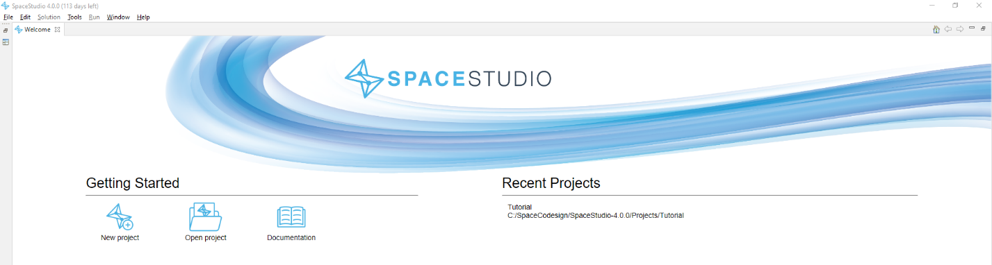
Figure 2.1 SpaceStudio’s welcome page#
2.1.3. Architecture Editor#
The main view of SpaceStudio is the architecture editor. It is an interactive block design environment that allows the user to view the system, connections, and edit them as required.
Moreover, it offers flexibility on architectural choices (for instance, you can connect a device’s master interface to a free high-speed interface of a Zynq UltraScale+ MPSoC). This editor should feel familiar to system designers, as it shares the principles of downstream EDA design tools, such as MathWorks Simulink and Xilinx Vivado.
Many diagram views can be opened at once in tabs, allowing a user to work on an architecture while another one is being compiled. Toolbar actions, such as ‘Run Simulation,’ are context-sensitive. They automatically target the architecture currently open in your active editor. To perform an action on a specific design, ensure its architecture editor or architecture node is selected before clicking the button.
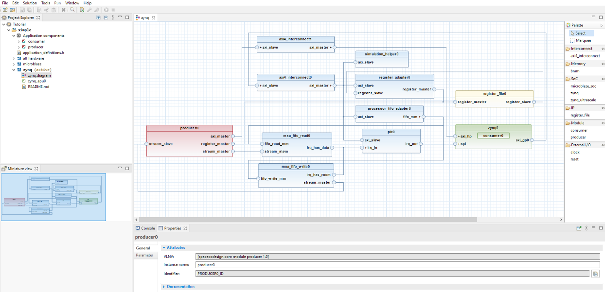
Figure 2.2 SpaceStudio’s architecture diagram view#
2.1.3.1. Diagram block color scheme#
Blocks in the SpaceStudio diagram are colored according to their type, as follows:
Color |
Description |
Example |
|---|---|---|
Red |
Module mapped to hardware |
|
Green |
Processor or module mapped to software |
|
Gray |
User-defined device |
|
Blue |
Component instance added automatically by SpaceStudio |
|
Yellow |
Component instance added manually by the user that is neither an application component or a processor |
|
2.1.3.2. Action on double clicking a block#
Double clicking a block in the diagram will perform an action depending on the block type, as follows:
For an application component instance (modules, devices), the related C++ source code file will be opened in the code editor.
For a hierarchical component instance, it will expand or collapse the hierarchy.
For a component instance with multiple grouped ports of the same type, it will collapse or expand all ports.
2.1.3.3. Hierarchical components#
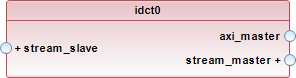
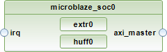
A hierarchical component is a component that contains sub-components. They show a ![]() icon when hovering over them. An example of both a collapsed and expanded hierarchical component is shown below.
icon when hovering over them. An example of both a collapsed and expanded hierarchical component is shown below.
Figure 2.3 Example of a hierarchical component in the diagram, in its collapsed state#
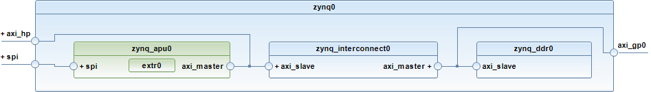
Figure 2.4 Example of a hierarchical component in the diagram, in its expanded state#
2.1.3.4. Grouped ports#
To make the diagram easier to read, ports of the same kind on a component instance are grouped together in the architecture diagram. By default, they are collapsed, but can be expanded to show each individual port.
A collapsed group shows a + icon, while an expanded group shows a - icon, as shown below.
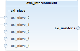
Figure 2.5 Example of a component instance with grouped ports. Expanded ports are shown on the left, while collapsed ports are shown on the right.#
Note
When connecting interfaces manually, the user can connect to a collapsed group. When doing so, SpaceStudio will use the first non-connected port in the group for the connection.
2.1.4. Project Explorer#
The project explorer displays relevant information about the currently opened project.
A project follows the following structure:
- Solutions: Group of architectures that share the same set of user-defined components and files.
Application Components: User-defined application intellectual property (IP), modules and devices.
Architectures: Diagram file (can be double-clicked to open the architecture diagram) and related SpaceStudio-generated files (virtual platform definitions, database, etc.). When in monitoring mode, the monitoring view can also be opened from here.
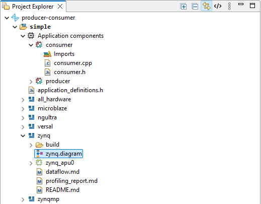
Figure 2.6 Example of the Project Explorer#
Note
From the project explorer, files can be opened by double-clicking on them. If a file is generated by SpaceStudio, it will be opened in a read-only editor.
2.1.5. Outline View#
The outline view displays the component instances found in the architecture in a tree view. Selecting a component instance in the outline view will synchronize the architecture editor to center the selected component instance. This feature is useful to quickly locate a component instance in a large architecture diagram.
The outline can also be used to rename, delete and copy-paste component instances through the right-click context menu.
Moreover, the outline view can be used to move module instances between hardware and software the same way as in the architecture diagram, by dragging and dropping the instance on a processor or on the root architecture node.
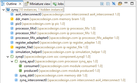
Figure 2.7 Example of the Outline View#
Finally, a “Quick Outline” tool can be invoked by pressing “Ctrl+O” in the architecture diagram. In addition to an outline of the component instances, it also provides a search bar to quickly find a component instance by name.
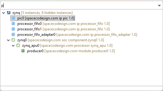
Figure 2.8 Example of the Quick Outline View#
2.1.6. Miniature View#
A large architecture may not fit in the architecture diagram view, even with zooming out. The miniature view provides a quick overview of the whole architecture, with a frame showing the current view in the full diagram view.
You can click and drag the frame in the miniature view to quickly navigate to different parts of the architecture diagram.
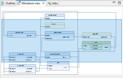
Figure 2.9 Example of the Miniature View#
2.1.7. Jobs View#
The Jobs View provides a real-time overview of all active and historical tasks within SpaceStudio. It tracks the execution status—such as Running or Terminated—for a variety of core actions, including:
Compilation
Simulation
FPGA Estimation
Architecture Implementation
FPGA-in-the-Loop
Each job functions as a parent container for a collection of specific processes. Navigation within this hierarchy dynamically updates the Console View:
Process: Selecting an individual process displays its specific output and detailed logs.
Job (Root Node): Selecting the job itself provides a high-level summary of the overall execution progress and final status.
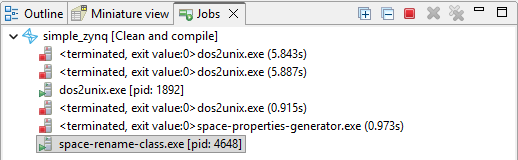
Figure 2.10 Example of the Jobs View#
2.1.8. Console View#
The console displays the logs of SpaceStudio. It shows the output of the different processes launched by SpaceStudio, such as the compilation and simulation processes, as well as the simulation’s text output.
Sub-consoles will be created for architecture implementation and FPGA estimation launches. To select between the different sub-consoles, click on the ![]() icon in the console’s toolbar, and select a console from the dropdown menu.
icon in the console’s toolbar, and select a console from the dropdown menu.
2.1.9. Properties View#
The properties view works with both the project explorer and the architecture diagram. When selecting a node from either of those, the properties view will update to show the properties of the selected element.
In general, the properties of a node from the project explorer display information about the related file, such as its path, size and type. Selecting a node from the architecture diagram allows the user to edit the properties of the related component instance.
2.1.10. Progress View#
The progress view shows the status of running jobs. SpaceStudio may start multiple jobs across different architectures at the same time, and each architecture may have multiple running processes. For instance, FPGA estimation can be run on an architecture while another architecture is being compiled for simulation. The progress view allows the user to keep track of all these processes and their status.
2.1.11. Metrics View#
The metrics view provides key hardware telemetry, including actual FPGA resource utilization and application runtime.
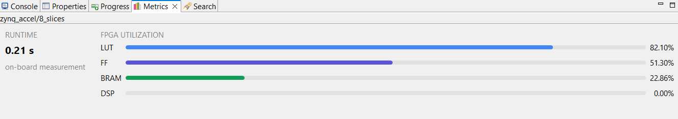
Figure 2.11 Metrics view#
2.2. Project management#
SpaceStudio projects are organized as a set of solutions, themselves being a set of architectures. In a solution, multiple architectures can be created to represent slight modifications to the system (for architecture exploration purposes for instance). An architecture contains all the information about the system design, such as the components, their connections and properties.
Solutions can be seen as multiple versions of the same application. For instance, the first solution may implement sequential execution, while the second implements the same application with multi-threaded execution. A solution contains a set of application components (modules and devices), and a set of architectures which describe instances of those application components, hardware/software mapping, and their connections.
2.2.1. Creating a new project#
Click on the File menu.
From the dropdown menu, click on New Project…. The following dialog will open.
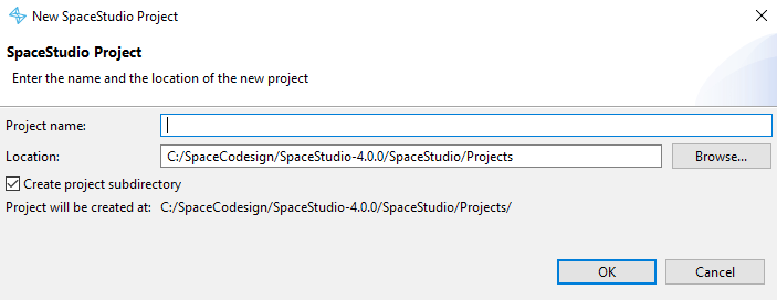
Figure 2.12 New project dialog#
In the dialog that opens, enter the name of the project, and choose the path where it will be created.
Click the OK button to create the project. If the corresponding option is enabled in the dialog, a subdirectory with the project name will be created in the selected path, and the project files will be created inside it. Otherwise, the project files will be created directly in the selected path.
2.2.2. Opening an existing project#
SpaceStudio projects are stored in a directory which contains a file with the .spacestudio extension. To open an existing project, follow the steps below:
Click on the File menu.
From the dropdown menu, click on Open Project….
In the file browser dialog that opens, navigate to the directory containing the project you want to open, select the file with the
.spacestudioextension.Click the Open button to open the project.
Only one project can be opened at a time in SpaceStudio. Trying to open another project while one is already opened will cause the currently opened project to be closed (with a prompt to save any unsaved changes) before opening the new project.
2.2.3. Closing a project#
To close the currently opened project, follow the steps below:
Click on the File menu.
From the dropdown menu, click on Close Project.
When you close a project, all open files will be closed, and you will be prompted to save any unsaved changes.
2.3. Solution management#
A solution represents an implementation of an application. There can be several solutions in a project. A solution is composed of a set of user-defined components (modules and devices), and a set of architectures which share the same set of user-defined components.
2.3.1. Creating a new solution#
Create a new project or open an existing one.
Open the Solution menu and click on New Solution…. The following dialog will open.
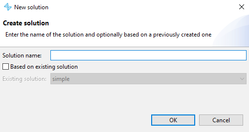
Figure 2.13 New solution dialog#
In the dialog that opens, choose a unique name for the solution.
If the box Based on existing solution is checked, select the solution you want to copy.
Click the OK button to create the solution.
2.3.2. Deleting a solution#
In the project explorer, right-click on the solution you want to delete and select “Delete”.
2.4. Application Components#
Application components, or application-specific user-defined functions, are programming elements with implementations defined by the system designer. An application component can be a functional or non-functional element of the application. In the case of a non-functional element, the application component implementation is composed of computation timing and communication budget based on the application specification.
2.4.1. Modules#
Modules are user-defined computational components that implement specific application tasks or algorithms. Each module is written in C/C++ and can be flexibly mapped to either hardware implementation (synthesized to RTL via HLS tools and implemented in FPGA fabric) or software implementation (compiled as threads or processes running on embedded processor cores). This hardware-software flexibility enables rapid design space exploration and performance-area trade-off analysis.
2.4.1.1. Creating a module#
Create a new project or open an existing one.
Create a new solution or open an existing one (by selecting it in the project explorer).
Open the Solution menu and click on New Module…. The following dialog will open.
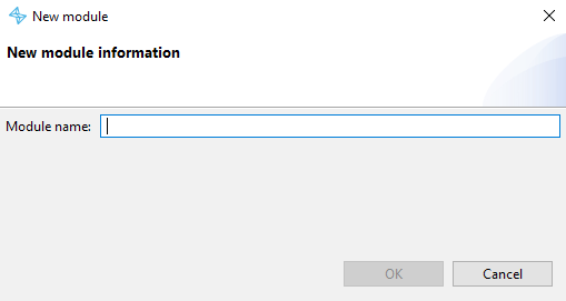
Figure 2.14 New module dialog#
In the dialog that opens, choose a unique name for the module.
Click the OK button to create the module.
The newly created module will be added to the list of application components in the project explorer, and will be made available in the toolbox of the architecture diagram.
2.4.1.2. Removing a module#
Before removing a module, make sure that the module is not instantiated in any architecture. If it is, SpaceStudio will not allow you to remove it, and will prompt you to first remove all instances of the module from the architectures.
In the project explorer, select and expand the solution containing the module you want to remove.
Expand the Application Components section to show the list of modules.
Right-click on the module you want to remove and select “Delete”.
2.4.1.3. Manage imports for a module#
Modules can depend on external source files, in addition to their own module header and source files. They can be managed using the following steps:
In the project explorer, select and expand the solution containing the module you want to manage imports for.
Expand the Application Components section to show the list of modules.
Right-click on the module you want to manage imports for and click either Import File… or Import Folder… depending on whether you want to import a single file or a whole folder. The corresponding file browser dialog will open.
In the file browser dialog, select the file or folder you want to import and click the Open button.
2.4.1.4. Manage toolchain build options for a module#
Modules can have specific compilation and linker preferences (for instance, to link a software module to a specific library). These preferences can be managed using the following steps:
In the project explorer, select and expand the solution containing the module you want to manage toolchain build options for.
Expand the Application Components section to show the list of modules.
Right-click on the module you want to manage toolchain build options for and click on Toolchain Build Options…. The following dialog will open.
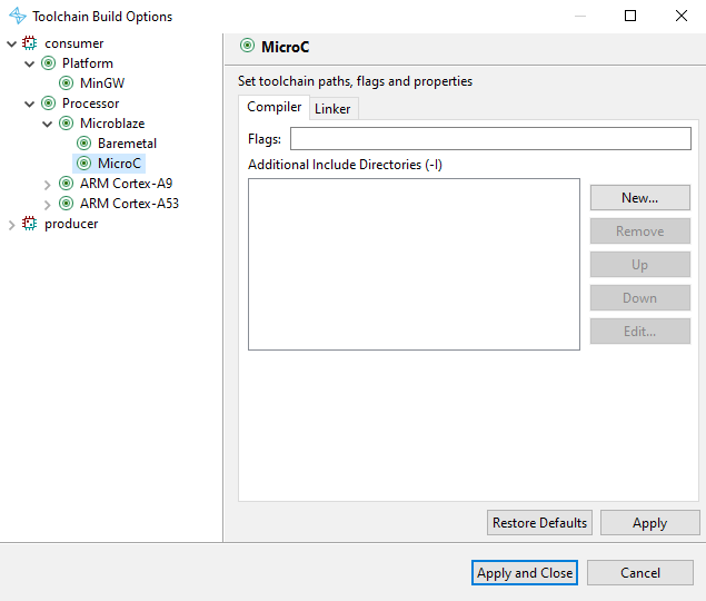
Figure 2.15 Module toolchain build options dialog#
Configure the compilation and linker options in their corresponding tabs.
Click the OK button to save the changes.
2.4.2. Devices#
Devices are user-defined hardware components representing custom peripherals and I/O interfaces in the system. Unlike modules (which can be mapped to hardware or software), devices are always implemented as hardware IP blocks. Devices communicate via memory-mapped interfaces conforming to standard bus protocols (typically AXI4 or AXI4-Lite), and can be configured as either slave devices (accessed by processors or master modules) or master devices (capable of initiating bus transactions, such as DMA controllers or network interfaces).
2.4.2.1. Creating a device#
Create a new project or open an existing one.
Create a new solution or open an existing one (by selecting it in the project explorer).
Open the Solution menu and click on New Device…. The following dialog will open.
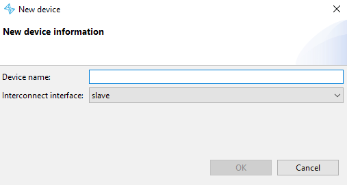
Figure 2.16 New device dialog#
In the dialog that opens, choose a unique name for the device.
Select the type of the device’s primary interface (slave or master).
Click the OK button to create the device.
The newly created device will be added to the list of application components in the project explorer, and will be made available in the toolbox of the architecture diagram.
2.4.2.2. Removing a device#
Before removing a device, make sure that the device is not instantiated in any architecture. If it is, SpaceStudio will not allow you to remove it, and will prompt you to first remove all instances of the device from the architectures.
In the project explorer, select and expand the solution containing the device you want to remove.
Expand the Application Components section to show the list of devices.
Right-click on the device you want to remove and select “Delete”.
2.4.2.3. Manage imports for a device#
The imports of a device are managed the same way as for modules. See Manage imports for a module for more details.
2.4.2.4. Manage toolchain build options for a device#
Toolchain build options for a device are managed the same way as for modules. See Manage toolchain build options for a module for more details.
2.5. Architectures#
An architecture represents a design scenario for a solution. These scenarios are composed of application component instances (modules and devices) mapped onto a system architecture. Thus, an architecture contains the architectural details regarding a specific design (component instances, their connections and properties).
For example, a user may decide to implement two variations on the same application: one with a single processor and another one with two. A solution contains as many architectures as the user wants to create to explore different design scenarios.
2.5.1. Creating an architecture#
To create a new architecture, at least one solution must be created.
Create a new solution or open an existing one (by selecting it in the project explorer).
Open the Solution menu and click on New Architecture…. The following dialog will open.
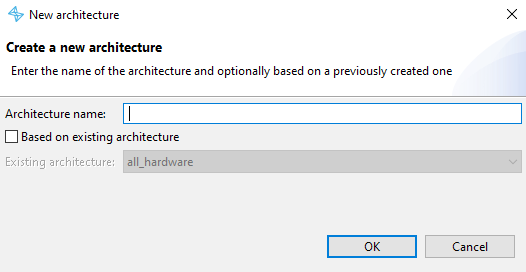
Figure 2.17 New architecture dialog#
In the dialog that opens, choose a unique name for the architecture.
If the box Based on existing architecture is checked, select the architecture you want to copy.
Click the OK button to create the architecture.
2.5.2. Removing an architecture#
In the project explorer, select and expand the solution containing the architecture you want to remove.
Select the architecture you want to remove, right-click on it and click Delete.
Note
The architecture will be deleted permanently from the project, and all related files will be removed from the disk.
2.5.3. Editing an architecture#
To modify an architecture, you must open its architecture diagram. To do so, expand the architecture node in the project explorer and double-click on the diagram file. The architecture diagram will open in a new tab, and you can edit it as required.
2.5.3.1. The Architecture Editor#
The architecture editor is the central design interface of SpaceStudio. It enables the user to:
Instantiate application components (user-defined modules and devices) and library IP components (interconnects, processors, memory controllers, timers, DMA engines, etc.).
Configure architectural parameters and adjust component instance properties through the integrated properties view.
Establish connections between component interfaces (ports) to define communication pathways and memory-mapped relationships.
Specify hardware-software partitioning by mapping computational modules either to hardware implementation (RTL/HLS) or to software threads running on processor cores.
The architecture editor works in conjunction with the properties view which shows the parameters for the component instance currently selected in the architecture diagram.
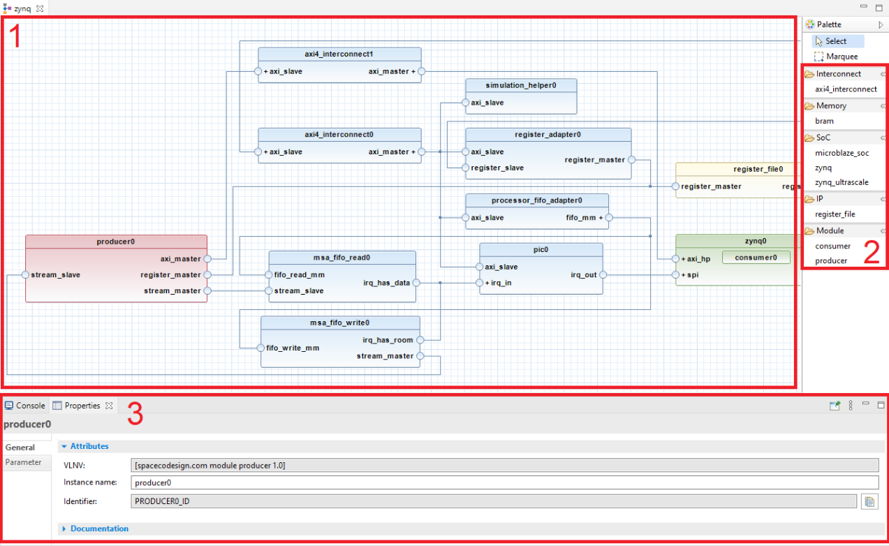
Figure 2.18 Architecture editor view#
In the figure Architecture editor view, section number 1 is the diagram editor itself. This editor displays the complete virtual platform in a block design graphical interface with which the user can directly interact.
Section number 2 contains the library components that the user can instantiate. It is made up of both platform components (IPs provided by SpaceStudio) and application components (defined by the user in the solution). To instantiate a component in the architecture diagram, simply drag and drop it from the library to the diagram.
Section number 3 is the properties view, which displays the parameters for the component instance currently selected in the architecture diagram. It is not part of the architecture editor per se, as it can also be used to edit properties of elements from the project explorer. However, it is an essential part of the workflow when editing an architecture, as it allows the user to adjust the properties of component instances in the architecture diagram.
2.5.3.1.1. Instantiate a component in an architecture#
To instantiate application components and platform IPs:
Open the architecture editor for the architecture you want to edit.
In the library section of the architecture editor, select the component you want to instantiate and drag and drop it in the diagram.
Technical close-up
SpaceStudio supports instantiating the same module multiple times. Each instance will use the same module implementation which can be parametrized using user-defined properties. Moreover, different instances of the same module can differentiate their behaviour by using the INDEX global macro defined by SpaceStudio. More details about it can be found in the SpaceLib API documentation.
2.5.3.1.2. Parameterize a component instance#
Component instances in the architecture have parameters associated to them which can be modified using the properties view. To inspect and modify the parameters of a component instance:
Open the architecture diagram containing the component instance you want to parameterize.
Click on the component instance in the diagram to select it. The properties view will update to show the parameters of the selected component instance.
In the properties view, modify the parameters as required.
2.5.3.1.3. User-defined parameters#
The user can add user-defined parameters (i.e. key-value pairs) to module and device instances. When a module or device is instantiated in the architecture, the value of each user-defined parameter can be set for the instance in the properties view, and each instance can have different values for the same user-defined parameter.
User-defined parameters are automatically injected into the module’s compilation context as C preprocessor macros (#define directives), making them accessible throughout the module’s source code at compile time. This mechanism enables conditional compilation, parameterized buffer sizes, and configuration constants. SpaceStudio automatically generates these macro definitions during the build process—users should not manually add #define statements for these parameters in source code, as this would create conflicts and redefinition errors.
An example of a user-defined parameter in the properties window is shown below, in the red square.
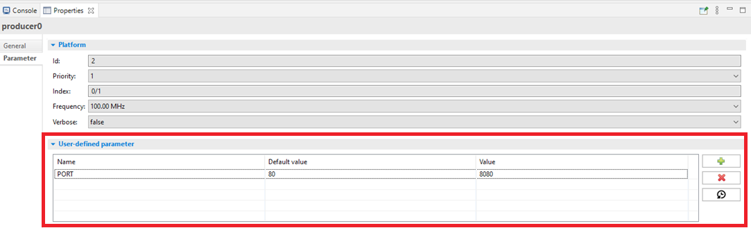
Figure 2.19 Example of a user-defined parameter in the properties view#
To add a new user-defined parameter to a module or device, follow the steps below:
In the project explorer, select and expand the solution containing the module or device you want to add a user-defined parameter to.
In the Application Components section, select the module or device you want to add a user-defined parameter to.
In the properties view, go to the Properties tab.
Click on the
 button.
Double click in the Name column of the newly created parameter to edit its name, and press “Enter” to save it.
Do the same for the Default value column.
Note
The actual value of a user-defined parameter for a specific instance of the module or device can be set in the properties view when the instance is selected in the architecture diagram. The value set for an instance will override the default value defined for the parameter.
Tip
In component instances, you can restore the default value of a user-defined parameter by selecting its row, then clicking on the ![]() icon on the right of the properties view.
icon on the right of the properties view.
Tip
To remove a user-defined parameter, select its row in the properties view, then click on the ![]() icon on the right of the properties view.
icon on the right of the properties view.
2.5.3.1.4. Memory initialization#
Memory component instances (such as BRAM or external DRAM) can be preloaded with initialization data to simplify simulation setup and avoid manual memory loading during runtime. This feature is particularly useful for preloading lookup tables, configuration data, firmware images, or test vectors. The user provides a JSON configuration file describing the memory initialization layout. Note that this feature is specific to simulation environments; memory initialization for FPGA implementation follows a different workflow using the EDA tool’s memory initialization mechanisms.
To initialize a memory component instance with a data file, follow the steps below:
In the architecture diagram, select the memory instance you want to initialize.
In the properties view, go to the Parameter tab.
In the Memory initialization field highlighted in the red square in the figure below, enter the path to the data file you want to use for memory initialization.
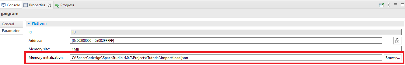
Figure 2.20 Memory initialization field in the properties view#
The provided file must be in the JSON format, and describes how the memory should be initialized. An example of such a file is shown below.
 1{
 2    "memory_regions" : [ {
 3        "offset" : {
 4            "long" : 0
 5        },
 6        "bytes" : {
 7            "string" : "whole_file"
 8        },
 9        "source_type" : "file",
10        "source" : {
11            "com.spacecodesign.avro.file_source" : {
12                "file" : "%project_directory%/import/image/jpeg1.jpg",
13                "offset" : 0
14            }
15        }
16    }, {
17        "offset" : {
18            "string" : "at_end_of_last_loaded_memory_region"
19        },
20        "bytes" : {
21            "long" : 4
22        },
23        "source_type" : "immediate",
24        "source" : {
25            "long" : 255
26        }
27    }, {
28        "offset" : {
29            "string" : "at_end_of_last_loaded_memory_region"
30        },
31        "bytes" : {
32            "long" : 4
33        },
34        "source_type" : "random",
35        "source" : null
36    } ]
37}
In this example, the first memory region starts at 0 (offset=0) and will load the whole file (bytes=whole_file) from a source file (source_type=file). The file path can use the %project_directory% token, which is replaced by the project directory (where the .spacestudio file is located).
The second memory region to be initialized will start at the end of the previous section (offset=at_end_of_last_loaded_memory_region) and 4 bytes (bytes=4) of immediate (source_type=immediate) value 255 (source=255) will be loaded in it.
The last memory region will start at the end of the previous section too (offset=at_end_of_last_loaded_memory_region) and will load 4 bytes (bytes=4) of random data (source_type=random).
2.5.3.1.5. Removing a component instance from an architecture#
To remove a component instance from an architecture, simply hover over the instance in the architecture diagram. A menu will show at the top right. In it, click the ![]() icon to remove the instance from the architecture.
icon to remove the instance from the architecture.
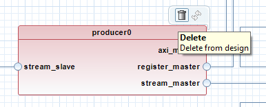
Figure 2.21 Remove instance menu in the architecture diagram#
Tip
Alternatively, you can select the instance in the architecture diagram and press the “Delete” key on your keyboard to remove it from the architecture.
2.5.3.1.6. Connecting component instances#
SpaceStudio features intelligent automatic connection inference that analyzes component interface types and automatically establishes appropriate connections when components are instantiated. Additionally, SpaceStudio automatically instantiates necessary infrastructure components to enable communication. For example, if a module needs to access a BRAM (Block RAM) but no interconnect fabric exists in the current architecture, SpaceStudio will automatically instantiate an AXI4 interconnect, connect the module’s master interface to the interconnect, and connect the BRAM’s slave interface to the interconnect—creating a complete, functional memory access path.
While SpaceStudio provides extensive automation, the system designer retains full control over architectural decisions. Any automatically-generated connections or component instantiations can be manually overridden, deleted, or reconfigured. SpaceStudio’s automation follows industry best practices and typical design patterns, so in most scenarios, manual intervention is unnecessary—but the flexibility is available when specialized configurations are required.
To make manual connections in the architecture diagram, click on a disconnected port and drag and drop the connection to the port you want to connect to.
For example, the port axi_master below is disconnected. We can connect it to compatible ports of other component instances by dragging and dropping a connection from it to the compatible port.

Figure 2.22 Example of a disconnected port in the architecture diagram#
Note
The cursor will change from a pointer to a hand when hovering on a valid destination port to connect to. If the destination port is not compatible, the connection will not be allowed and the cursor will remain an arrow.
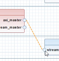
Figure 2.23 Example of an invalid destination port in the architecture diagram. The cursor remains an arrow, and the connection is not allowed.#
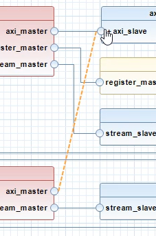
Figure 2.24 Example of a valid destination port in the architecture diagram. The cursor changes to a hand, and the connection is allowed.#
2.5.4. Configuration for Launch Mode#
SpaceStudio provides two primary launch modes: Simulator and FPGA-in-the-loop (FIL). A configuration wizard is used to manage these settings. Once a configuration is defined for a specific architecture, it can be utilized across three execution modes: Run, Debug, and Profile.
To create a configuration:
Right-click the architecture from the project explorer view.
Select , , or .
From the sub-menu, select .
- In the configuration window, create a new launch configuration:
To simulate: Right-click Execute on Simulation and select New Configuration.
To execute on hardware: Right-click Execute on FPGA and select New Configuration.
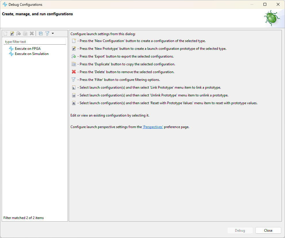
Figure 2.25 The Launch Configuration Wizard interface#
Note
A default name will be assigned to the configuration, which can be modified in the name field at the top of the window.
Refer to Simulation for simulation parameters and FPGA-in-the-loop (FIL) for FPGA execution details.
2.5.4.1. Simulation#
General
- Architecture
The specific architecture associated with this configuration.
Execution
- Simulation timeout
When enabled, enforces a maximum simulation duration (in simulated time). If the simulation does not complete within this timeout period, SpaceStudio will terminate the execution automatically. This prevents indefinite hangs caused by software deadlocks or infinite loops.
- Wall clock timeout
When enabled, enforces a maximum real-time duration for FPGA execution (in minute). If the application does not complete within this timeout period, SpaceStudio will terminate the execution to prevent indefinite hangs caused by software deadlocks or infinite loops.
- Hook location
Specifies a directory path containing custom hook files that modify simulation behavior. When enabled, SpaceStudio will load and integrate the hook files listed in the table below during the build process.
File |
Description |
|---|---|
sim_free_section.cpp |
Custom C++ code appended to the generated main.cpp file used in simulation. Use this to add initialization code, custom logic, or cleanup routines. |
2.5.4.2. FPGA-in-the-loop (FIL)#
FIL execution requires the following hardware and software environment setup:
The FPGA development board must be powered on.
An embedded Linux operating system must be running on the target processor (typically ARM Cortex-A cores on Zynq/Zynq UltraScale+ platforms).
A public SSH key must be provisioned into the target’s filesystem (usually
~/.ssh) to enable passwordless authentication.A JTAG programming cable must physically connect the FPGA board to the host computer for bitstream programming.
The board must be accessible via TCP/IP network with proper routing configured between the host and target.
2.5.4.2.1. Parameters#
General
- Architecture
The specific architecture associated with this configuration.
- Electronic Design Automation (EDA) tool
The EDA toolchain used for RTL synthesis, place-and-route, and bitstream generation (e.g., Xilinx Vivado, AMD Vitis).
- Board
The target FPGA development board platform. Available board options are filtered based on the selected architecture’s processor configuration and the capabilities of the chosen EDA tool.
- Number of threads
The maximum number of concurrent CPU threads allocated to the EDA tool for parallel processing during synthesis, implementation, and timing analysis. Higher thread counts reduce build time on multi-core systems.
HLS Options
- High-level synthesis
The High-Level Synthesis (HLS) compiler used to translate C/C++ hardware module implementations into synthesizable RTL (Register Transfer Level) code (e.g., Vitis HLS, Catapult HLS).
- Module instances to synthesize
A list of all module instances mapped to hardware in the current architecture. Use the checkboxes to selectively enable HLS compilation for specific modules. Unchecked modules will use pre-existing RTL implementations or be excluded from synthesis.
Execution
- Wall clock timeout
When enabled, enforces a maximum real-time duration for FPGA execution (in minute). If the application does not complete within this timeout period, SpaceStudio will terminate the execution to prevent indefinite hangs caused by software deadlocks or infinite loops.
- Hook location
Specifies a directory path containing custom hook files that modify FIL behavior. When enabled, SpaceStudio will load and integrate the hook files listed in the table below during the build process.
File |
Description |
|---|---|
create_project_hook.tcl |
Tcl script sourced at the end of the generated EDA project creation script. The script must define a spacestudio_create_project_hook proc, which is called right after being sourced, while the project is still open. |
Setup
- Host IP
The IP address of the host development machine on the network interface connected to the FPGA board. This address must be routable from the target’s network configuration.
- SSH private key
The absolute filesystem path to the SSH private key file (the private half of the RSA key pair) corresponding to the public key provisioned on the target. This key is used to establish secure, authenticated connections to the embedded Linux system.
Tip
Use the Test connection button to validate the complete communication path to the target FPGA before launching execution. This diagnostic verifies that the board is correctly configured and accessible through both the JTAG interface (for programming) and the TCP/IP network (for SSH communication and file transfer).
Note
FIL supports RSA SSH-2 protocol public keys (identified by the ssh-rsa prefix in the key file). For enhanced security against brute-force attacks, we recommend generating and using 4096-bit RSA keys instead of the default 2048-bit keys.
2.5.4.2.2. Target Provisioning#
While the launch configuration defines the host-side parameters, the physical target must also be prepared. To enable FIL execution, the FPGA target must be provisioned with SSH authentication credentials and network configuration.
Note
The host machine and the target FPGA board must be connected to the same IP network subnet to enable bidirectional communication between the development environment and the embedded Linux system.
To configure SSH public key authentication and network settings (refer to Figure 2.26):
Open the Architecture Editor and select the processor instance running the embedded Linux operating system.
In the Properties view, navigate to the Linux tab.
- Configure SSH Authentication:
Under the File System section, enable Enable SSH public key to provision the public key into the target’s filesystem during image generation.
Enter the absolute path to your SSH public key file (the public half of your RSA key pair, typically with a
.pubextension).
- Configure Network Interface:
Under the Network section, enter the static IP address, subnet mask, and gateway that match your local network topology and are compatible with the host’s network configuration.
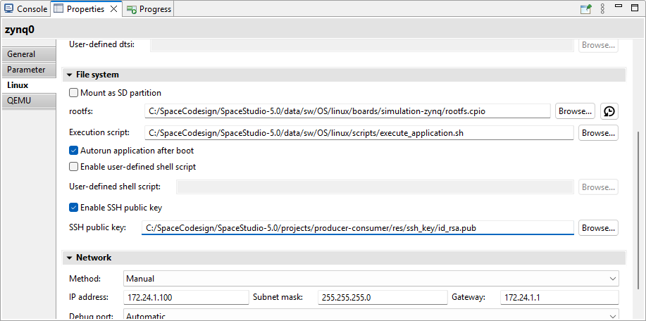
Figure 2.26 Configuring SSH and Network settings in the Architecture Editor Properties view#
2.6. Architect Dashboard#
The Architect Dashboard provides a high-level overview of all architectures created within the project. From here, users can configure and batch-execute architectures using the FPGA-in-the-loop workflow. As execution progresses, performance metrics automatically populate the dashboard.
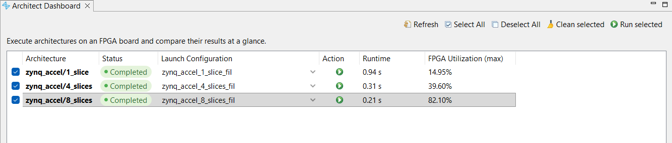
Figure 2.27 Architect Dashboard#
2.7. Real-Time Operating Systems#
SpaceStudio supports targeting various real-time operating systems (RTOS) when building embedded software for processor cores. You can use the properties view to select the RTOS you want to target for each processor instance in your architecture.
2.7.1. Supported RTOS Targets#
2.7.1.1. Baremetal#
SpaceStudio includes a baremetal runtime environment—a minimal, non-preemptive execution environment without an operating system kernel. This lightweight runtime uses polling-based I/O and cooperative multitasking to eliminate context switching overhead, making it suitable for simple, deterministic applications. Due to the absence of a scheduler, the baremetal runtime supports only a single task (thread of execution) per processor core.
Supported platforms
Xilinx Zynq MicroBlaze, Zynq (AMP mode), Zynq UltraScale+ (AMP mode on Cortex-A cores)
2.7.1.2. Micrium µC/OS-II#
µC/OS-II is a multi-tasking RTOS developed by Micrium. Multiple software tasks can be mapped to a single processor core when targeting this RTOS. µC/OS-II comes installed with SpaceStudio and can be evaluated for 45 days free of charge. You are legally required to purchase a license from Micrium to use µC/OS-II in any commercial application. Please contact Micrium for more information about your µC/OS-II license rights and obligations.
Supported platforms
Xilinx MicroBlaze, Zynq (AMP mode), Zynq UltraScale+ (AMP mode on Cortex-A cores)
2.7.1.3. Linux#
Linux is a full-featured, general-purpose operating system (non-real-time by default) providing process management, virtual memory, filesystems, networking, and extensive driver support. Linux requires hardware support for virtual memory management (MMU - Memory Management Unit), restricting its availability to application-class processors. On Xilinx/AMD platforms, Linux is supported exclusively on Cortex-A cores (Zynq-7000, Zynq UltraScale+, Versal) which include MMU hardware. Cortex-R cores on these platforms lack MMU support and cannot run Linux.
Linux operation in SpaceStudio is configured for SMP (Symmetric Multi-Processing) mode, where a single kernel instance manages all available CPU cores, enabling automatic load balancing and inter-core communication.
Supported platforms
Xilinx Zynq, Zynq UltraScale+ (Cortex-A cores only), Versal (Cortex-A cores only)
2.7.1.4. RTEMS 6#
RTEMS (Real-Time Executive for Multiprocessor Systems) is an open-source, hard real-time operating system designed for deterministic embedded applications. RTEMS provides priority-based preemptive scheduling, inter-task communication primitives (semaphores, message queues, events), memory protection (on supported hardware), filesystem support, and networking capabilities. RTEMS features comprehensive documentation and active community support, making it suitable for aerospace, automotive, and industrial control applications requiring real-time guarantees.
Supported platforms
Xilinx Zynq (SMP mode), NanoXplore NG-ULTRA (SMP mode)
2.7.1.5. FreeRTOS#
FreeRTOS is a lightweight, open-source real-time operating system kernel designed for resource-constrained embedded systems. FreeRTOS emphasizes small memory footprint, simplicity, and portability across diverse processor architectures. It provides preemptive priority scheduling, tasks (threads), queues, semaphores, and software timers—core RTOS primitives sufficient for many embedded applications. FreeRTOS is particularly well-suited for microcontrollers and small embedded processors where code size and RAM usage are critical constraints.
Supported platforms
Xilinx Zynq UltraScale+ (SMP mode on Cortex-R cores only), Versal (SMP mode on Cortex-R cores only)
2.8. Settings and Preferences#
The SpaceStudio environment has centralized all preferences and options to a single page to make it easier for the user to configure the environment. They are separated into two levels. First, the SpaceStudio preferences which include global preferences for the development tool. The second level is the Architecture Preferences, related to a specific architecture. Multiple architectures within the same solution can have different preferences.
To access the preferences, click on the Tools menu and select Preferences…. The following dialog will open.
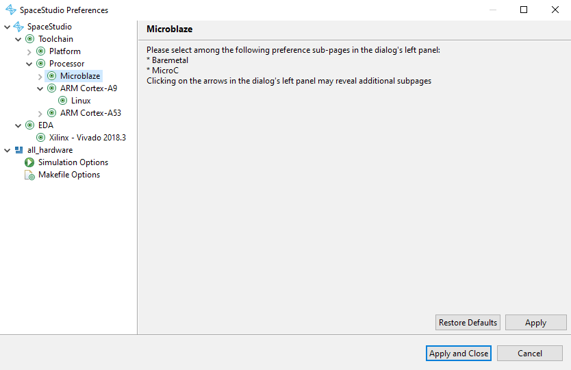
Figure 2.28 Preferences dialog#
2.8.1. SpaceStudio global preferences#
This section presents the following global preference categories:
Toolchain: Pages related to the configuration of various toolchain options for the hardware platform (i.e., compiling the hardware simulation), as well as for software on processors. One page is available for each supported platform toolchain, as well as for each supported processor toolchain. To speed up compilation, a compilation cache is enabled by default and can be disabled through these pages.
EDA: Pages related to the configuration of EDA tools used for architecture implementation and FPGA estimation. One page is available for each supported EDA tool.
2.9. Simulation#
SpaceStudio allows the user to simulate the system to verify its functionality. The steps required to execute the simulation are as follows:
File generation: SpaceStudio generates the virtual platform (hardware and software simulation sources, platform definition files, etc.) based on the architecture design.
Compilation: The generated files are compiled to produce the simulation executable.
Simulation execution: The simulation executable is launched, and the system behavior can be observed through the simulation logs in the console view.
2.9.1. Compilation#
The compilation operation compiles all user-defined application components along with the SystemC virtual platform code generated by SpaceStudio, producing an executable simulation binary:
Select the target architecture from the project explorer view
Click the
 icon in the toolbar to initiate compilation
Tip
If you encounter linking errors or suspect stale object files from previous builds, perform a clean build. Navigate to the Tools menu and select Clean generated files to remove all intermediate object files and executables before recompiling. This ensures a fresh build from source.
2.9.2. Executing the simulation#
To launch the simulation, follow these steps:
Right-click the architecture from the project explorer view
From the menu, select Run As then click on Launch in a simulator
The simulation will be compiled if needed, then start, and the simulation logs will be displayed in the console view.
2.9.2.1. Specificities of Linux simulation#
After the Linux kernel completes booting and the init process finishes, you will have access to an interactive command-line interface. However, if the Run Linux application automatically after boot option is enabled in the processor properties, the compiled application binary will execute automatically post-boot, potentially bypassing interactive shell access.
To run the Linux software application if not enabled to run automatically after boot, you can execute the following commands once the boot process is finished and you have access to the Linux command prompt:
cd /root
./<linux_application_executable>
Where <linux_application_executable> is the name of the Linux application executable file generated by SpaceStudio. You can find it in the /root directory in the simulated Linux file system (find its exact name by running ls /root and searching for a file with a .elf extension).
SpaceStudio automatically provisions the following directories and files into the embedded Linux filesystem image:
/root/drivers: Contains platform-specific Linux kernel modules (device drivers) and an initialization shell script automatically generated by SpaceStudio. These kernel modules provide hardware abstraction for the custom IP blocks in your architecture. The drivers are regenerated after each architecture modification and are automatically loaded during the boot sequence via the initialization script.
2.9.3. Stopping the simulation#
A simulation terminates gracefully when user code calls the sc_stop() SystemC function, which signals the simulation kernel to complete the current delta cycle, flush all pending events, finalize performance monitoring data collection, and perform clean shutdown of the virtual platform. Alternatively, the user can click the ![]() icon in the console toolbar to manually halt execution.
icon in the console toolbar to manually halt execution.
Manual termination is useful for stopping long-running or misbehaving simulations stuck in infinite loops. When triggered, SpaceStudio first attempts a graceful shutdown by sending a termination signal to the simulation process. If the process does not respond within a reasonable timeout (typically a few seconds), SpaceStudio escalates to a forceful kill operation to immediately terminate the process.
Note
The results of the simulation displayed in the console using printf/SpacePrint are displayed in the output view, at the bottom of the SpaceStudio window (may require to select the tab to show it instead of the properties view).
Warning
Forcefully terminating a simulation may result in incomplete or corrupted output data, including partial monitoring traces, unflushed log buffers, and incomplete performance metrics. For reliable results and complete data collection, design your application code to call sc_stop() when processing is complete, ensuring all simulation infrastructure can perform proper cleanup.
2.9.4. Debugging in simulation#
Application components in SpaceStudio are implemented in C/C++, enabling standard debugging workflows using industry-standard debuggers such as GDB (GNU Debugger). SpaceStudio integrates Eclipse CDT (C/C++ Development Tooling) to provide a graphical debugging interface with breakpoints, variable inspection, call stack navigation, and step-through execution.
SpaceStudio supports simultaneous co-debugging of both hardware modules (running in the SystemC simulation environment) and software applications (executing on simulated processor cores), allowing comprehensive system-level debugging across the hardware-software boundary. The following figure shows two debuggers in action (one for hardware and one for software) :
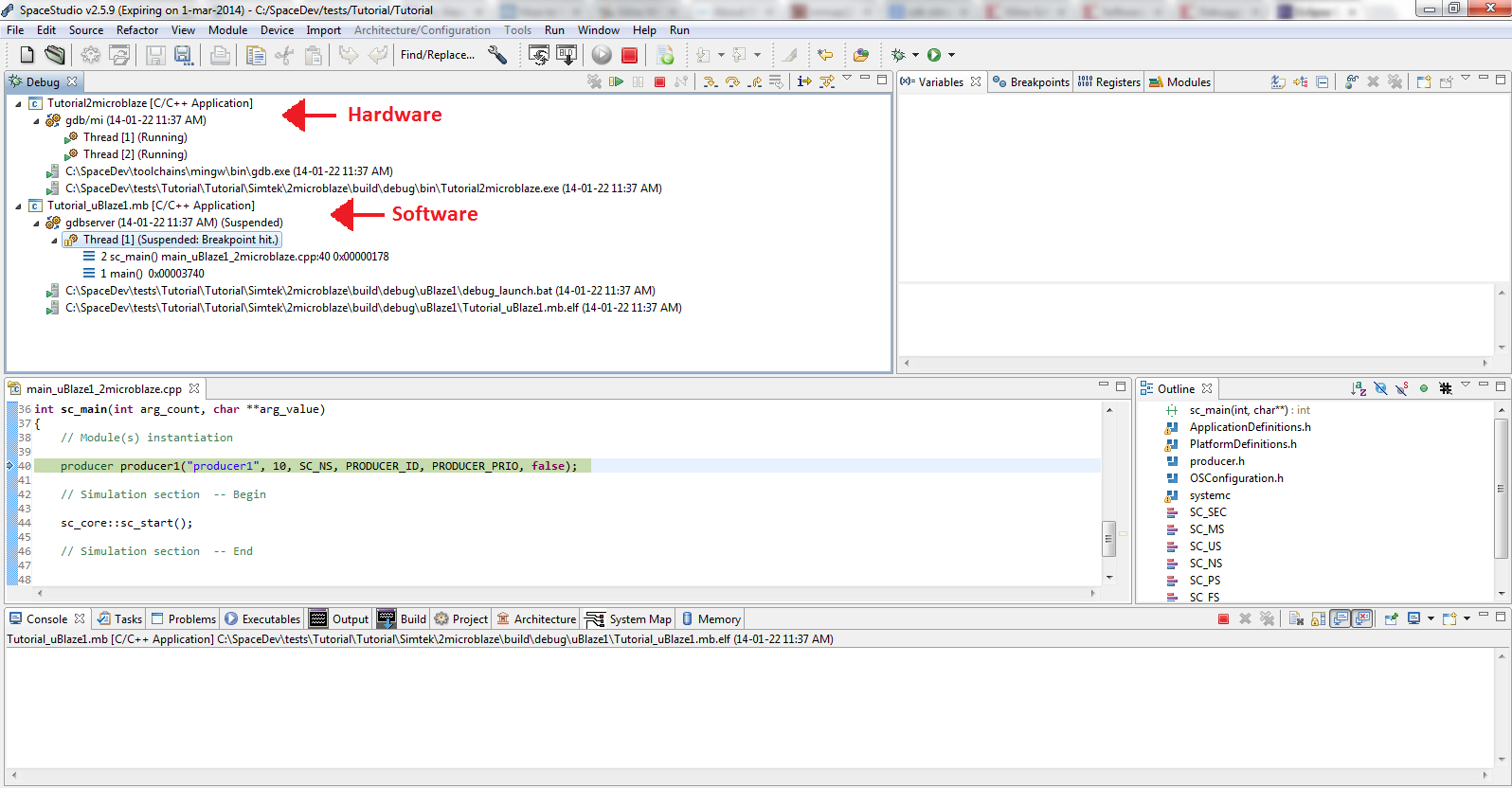
Figure 2.29 Example of co-debugging hardware and software in SpaceStudio#
To debug a simulation, you first need to set which components to debug in the architecture diagram. Debugging for a component is enabled when the bug icon is shown when hovering as seen in Figure 2.30. Debugging is disabled for a component when the bug icon is striked through as seen in Figure 2.31. To toggle debugging for a component, simply click on the bug icon in the component instance in the architecture diagram.
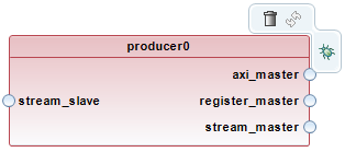
Figure 2.30 Debugging enabled for a component instance in the architecture diagram#

Figure 2.31 Debugging disabled for a component instance in the architecture diagram#
Debug for instances mapped to a processor is enabled by enabling debug for the processor instance in the architecture diagram, as shown in Figure 2.32.
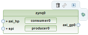
Figure 2.32 Debugging enabled for a processor instance in the architecture diagram#
To start a debugging session, follow the steps below:
Enable debugging for the components you want to debug by clicking on the bug icon in their instances in the architecture diagram.
Right-click the architecture from the project explorer view
From the menu, select Debug As then click on Launch in a simulator
After compilation and when the simulation starts, you will be prompted to switch to the debug view. Agree to switch to the debug view, and the debugging perspective will open with the GDB debuggers for the hardware and software components you enabled debugging for.
Note
The debugger automatically sets initial breakpoints at the entry point of each execution context: the sc_main function for the SystemC hardware simulation, and the main function for each embedded software application running on processor cores. From these breakpoints, you can use standard debugging controls—resume, step into, step over, step out, and user-defined breakpoints—to control execution flow and inspect program state, local variables, registers, and memory.
Important
You may be prompted by your firewall to allow GDB to accept incoming connections. This is required for the debugger to work, so make sure to allow it.
2.9.4.1. Software debugging on processors running Linux#
To debug software applications running on Linux-based processors (e.g., Zynq or Zynq UltraScale+ ARM cores), network connectivity must be enabled in the simulation. The debugging workflow uses a client-server model: GDB running on the host development machine connects via TCP/IP to a GDB server (gdbserver) process running within the simulated Linux environment. To enable network support for Linux simulation debugging:
Open the target architecture diagram
In the Architecture Editor, select the processor instance configured to run Linux
In the Properties view, navigate to the Linux tab
Under the Network section, ensure Method is set to any option other than Disabled (e.g., Manual or DHCP)
2.10. Performance Analysis and Monitoring#
The monitoring infrastructure enables detailed performance analysis and behavioral profiling of SpaceStudio simulations. During simulation execution, the monitoring system non-intrusively captures timestamped event traces including bus transactions (AXI read/write operations), inter-module communication (FIFO transfers, memory-mapped I/O), memory access patterns, processor utilization (active/idle cycles), and communication latencies. This trace data is stored in a database for post-simulation analysis.
Using the monitoring tools, developers can identify performance bottlenecks (saturated buses, memory contention, processor stalls), analyze task scheduling and parallelism, validate communication protocols, and optimize system architecture for throughput, latency, and resource utilization.
This feature is further described in the Monitoring documentation.
2.11. Version Information#
You can use the About SpaceStudio dialog to discover:
The version of SpaceStudio you are using.
The time left in a time-limited license.
To open the About SpaceStudio dialog:
Click the Help menu
From the dropdown menu, click on About SpaceStudio…. The following dialog will open.

Figure 2.33 About SpaceStudio dialog#
2.12. Frequently Asked Questions#
2.12.1. My simulation seems to hang. Why?#
This situation is usually caused by one of the following reasons:
There is an infinite loop in the user code. This doesn’t let the SystemC simulation engine schedule other processes, and thus the simulation appears to be hanging. Make sure to leave time for other processes by using the
hw_compute_latencyfunction or by adding communications.The simulation might be waiting for connections with software debuggers to be established with no success. Check the Debugging in simulation section for more details.
2.12.2. My simulation used to work before I mapped a module to software, and now it fails with an unexpected error message. Why?#
This situation is usually caused by one of the following:
The architecture’s executable might have been built using stale files. See answer to “Why does SpaceStudio keep ignoring my modifications?” for more details.
2.12.3. Why does SpaceStudio keep ignoring my modifications?#
If you edit the active architecture’s content with the architecture editor but when you run a simulation your recent changes are not reflected in the simulation, the following might be the cause:
After editing the architecture, you must re-generate the files and compile again for the changes to be taken into account in the simulation.
After you modify one of your own modules or devices, you need to regenerate and recompile the architecture.