3. Introduction to System Design#
3.1. SpaceLib#
SpaceLib is a C/C++/SystemC library that enables platform-based design of embedded systems targeting FPGA implementation. SpaceLib provides hardware abstraction APIs for communication, synchronization, and I/O operations, enabling a model-driven co-design methodology where application functionality is decoupled from architectural implementation.
3.1.1. Modules#
In SpaceLib, a module represents a function from your original application. To design a system in SpaceStudio, you decompose your application by identifying its constituent functions and extracting each function into a separate module. This one-to-one relationship between application functions and SpaceLib modules is the foundation of the design methodology.
Consider a typical application with sequential function calls:
void main() {
    data = read_input();
    processed_data = func_a(data);
    filtered_data = func_b(processed_data);
    result = func_c(filtered_data);
    write_output(result);
}
To create a SpaceLib design, each function (func_a, func_b, func_c) is extracted and implemented as an independent module. The sequential function call chain becomes a network of communicating modules.
Note
While the one-function-per-module approach is a logical starting point, designers have complete freedom in how they structure their modules. You may choose to:
Function Fusion: Combine multiple related functions into a single module to reduce communication overhead or simplify the design
Function Splitting: Decompose a complex function into multiple smaller modules for finer-grained parallelism or hardware/software partitioning
Hierarchical Modules: Create modules that internally call other functions or contain sub-components
Arbitrary Granularity: Define modules at whatever granularity best suits your application’s performance, complexity, and design goals
The function-to-module mapping is a design guideline, not a strict requirement. Experiment with different module decompositions to find the optimal balance for your specific application.
The key benefit of extracting functions into modules is enabling pipeline parallelism. In the original sequential application, func_c cannot begin until func_b completes, and func_b waits for func_a. By transforming each function into a module:
Module A (implements func_a) processes input data and streams results to Module B
Module B (implements func_b) simultaneously processes Module A’s previous output while Module A works on new input
Module C (implements func_c) processes Module B’s output concurrently with Modules A and B
This pipeline architecture enables overlapped execution: while Module C processes frame N, Module B processes frame N+1, and Module A processes frame N+2 simultaneously. Instead of waiting for each frame to complete all processing stages sequentially, multiple frames flow through the pipeline concurrently, significantly increasing throughput.
Once extracted into modules, each function can be independently mapped to either hardware or software. A module can be:
Software-mapped: Compiled as a task or thread executing on a processor (ARM Cortex, MicroBlaze, etc.)
Hardware-mapped: Synthesized to an FPGA hardware accelerator via High-Level Synthesis (HLS)
The same module source code works in both mappings without modification. This flexibility enables rapid design space exploration—you can evaluate different hardware/software partitioning options (e.g., accelerating performance-critical functions in hardware while keeping control functions in software) without rewriting code.
Technical close-up
When looking at the source code of a module, it is a C++ class that inherits from the abstract_module class. This abstract_module class is provided by SpaceLib. This base class offers the basic services that a module needs to communicate with the platform it will be connected to and read/write messages to/from other modules. Templates for defining modules are provided with SpaceStudio. See section sec_application_components for more information about creating modules.
3.1.2. Devices#
Devices are hardware peripherals and IP blocks that provide infrastructure and I/O services to the application. Unlike modules (which implement application-specific algorithms), devices represent hardware components with memory-mapped register interfaces. SpaceStudio supports two categories of devices: platform IP provided by SpaceLib, and user-defined devices created by designers.
3.1.2.1. Platform IP Devices#
SpaceLib provides a library of pre-characterized platform IP components for common infrastructure functions:
Memory Components: BRAM (Block RAM) and FIFO
Interconnect Fabric: AXI interconnect and adapter
System Components: Interrupt controllers, Timer, DMA engines, register files—provide system-level services
These platform IP components are instantiated from the SpaceStudio component library and automatically configured with appropriate address mappings and interconnect connections.
3.1.2.2. User-Defined Devices#
Designers can create custom devices to implement application-specific hardware peripherals or specialized I/O interfaces. User-defined devices are hardware-only components (always implemented in FPGA fabric, never software) with two architectural variants:
3.1.2.2.1. Slave-Only Device#
A slave device responds to read/write transactions from master components (modules or processors). The device exposes a memory-mapped register interface, allowing masters to:
Configure device operation through control registers
Transfer data to/from the device via data registers
Query device status through status registers
Common examples include custom sensor interfaces, configuration registers, or simple peripherals that react to processor commands.
3.1.2.2.2. Master-Slave Device#
A master-slave device includes both interfaces:
Slave Interface: Responds to configuration and control requests from processors or modules (similar to slave-only devices)
Master Interface: Initiates independent bus transactions to access memory or communicate with other devices
The master interface enables the device to perform autonomous operations without processor intervention. Common examples include:
DMA Controllers: Configured via slave interface, then autonomously transfer data between memory regions via master interface
Network Interfaces: Receive configuration via slave interface, then autonomously fetch/store packet data via master interface
Custom Accelerators with Memory Access: Configured via slave interface, then fetch input data and write results directly to memory
Master-slave devices enable offloading complex data movement operations from processors, improving system performance and reducing processor workload.
3.1.3. Messages and Communication Channels#
Inter-module and module-to-device communication in SpaceLib is implemented through message-passing abstractions that automatically adapt to the underlying hardware/software mapping. Communication channels abstract the physical interconnect infrastructure, allowing designers to specify data flow without concern for bus protocols, arbitration, or adapter logic.
Channel Connectivity:
Hardware Modules: Directly connected to communication channels via hardware interface protocols (AXI4-Stream for streaming, AXI4 for memory-mapped)
Software Modules: Indirectly connected through the host processor’s bus interface; SpaceLib runtime translates API calls into bus transactions
Channel Types and Topology:
Communication channels range from simple point-to-point connections to complex multi-master interconnect networks:
Point-to-Point FIFO: Low-latency streaming channel between two modules with configurable buffering
Shared Memory: Memory-mapped communication through BRAM or external DRAM
Register Files: Fast control and status exchange via register-based communication
Interconnect Fabrics: AXI4-based crossbar or bus matrix enabling multiple masters and slaves with automatic arbitration
SpaceStudio automatically instantiates the appropriate channel infrastructure based on module mapping and communication patterns, inserting necessary adapters, FIFOs, and interconnect components.
The following figure depicts the architectural concepts. Designers provide module and device implementation code (yellow), while SpaceLib and SpaceStudio automatically generate all infrastructure components and channels (blue).
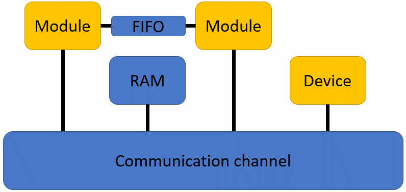
Figure 3.1 Modules, device, adapters, RAM Device and channel#
3.1.4. Simulation#
SpaceLib simulation serves as a functional validation platform, enabling designers to verify algorithmic correctness, data flow logic, and inter-module communication behavior before committing to physical FPGA implementation. The simulation environment provides rapid iteration for debugging application logic and validating system functionality.
SpaceStudio simulation is primarily designed for functional validation, not performance analysis. The simulation environment focuses on verifying:
Algorithmic Correctness: Validating that module implementations produce correct outputs for given inputs
Control Flow Logic: Verifying state machines, decision logic, and sequencing behavior
Inter-Module Communication: Testing data exchange patterns, synchronization, and protocol compliance
System Integration: Confirming that modules, devices, and interconnects interact correctly as a complete system
Software Functionality: Validating embedded software logic running on processor cores
3.1.4.1. Virtual platform#
A virtual platform is generated when the designer completes the hardware/software instantiation and mapping. In a virtual platform, slave devices connected to an interconnect require an address range which is a combination of base and high addresses. Address ranges in the generated virtual platform are contained in a generated file named bus_addresses.cpp. During the simulation, SpaceLib queries this file to retrieve the address range for components.
The following figure shows an example of typical contents of bus_addresses.cpp where each hardware component is assigned a valid address range:
 1#include "spacelib_global.h"
 2
 3extern spacelib_global::bus_container axi4_interconnect0_container;
 4
 5spacelib_global::bus_connection axi4_interconnect0_connections[] = {
 6    { 0, { 1, 0x00010000, 0x00017FFF }, 0 },
 7    { 1, { 7, 0x00018000, 0x00018FFF }, 0 },
 8    { 2, { 11, 0x00019000, 0x00019FFF }, 0 },
 9    { 3, { 14, 0x0001A000, 0x0001AFFF }, 0 },
10    { 4, { 10, 0x0001B000, 0x0001BFFF }, 0 },
11    { 5, { 13, 0x0001C000, 0x0001CFFF }, 0 }
12};
13
14spacelib_global::bus_container axi4_interconnect0_container = { 6,
15    axi4_interconnect0_connections };
16
17spacelib_global::addressable_id reserved_address_range[] = {};
18spacelib_global::addressable_id_container reserved_address_range_container = { 0,
19    reserved_address_range };
20
21spacelib_global::addressable_id addressable_component[] = {
22    { 14, 0x0001A000, 0x0001AFFF },
23    { 11, 0x00019000, 0x00019FFF },
24    { 10, 0x0001B000, 0x0001BFFF },
25    { 1, 0x00010000, 0x00017FFF },
26    { 13, 0x0001C000, 0x0001CFFF },
27    { 7, 0x00018000, 0x00018FFF },
28    { 8, 0x00000000, 0x0000FFFF }
29};
30
31spacelib_global::addressable_id_container addressable_component_container = {
32    7, addressable_component };
The process of generating the above file is handled by SpaceStudio. On the other hand, specifying constraints on address ranges is the responsibility of the designer. The designer has three options on how to specify the address range for components in the virtual platform:
The designer lets SpaceStudio generate all address ranges
The designer specifies all address ranges; or
The designer specifies some address ranges and lets SpaceStudio generate the remaining address ranges
For the first option, designer intervention is not needed as SpaceStudio will assign valid address ranges for all components. This is the default option for SpaceStudio.
For the second and last option, the designer needs to assign a valid address range for the components he wants to manage. This process is done by modifying the component’s properties in the opened diagram. This process is further explained in the SpaceStudio User Guide.
Prior to finalizing the generation of the virtual platform, SpaceStudio will perform several validations on the architecture. If the architecture contains errors (such as overlapping address ranges), errors will be reported to the designer, who can then correct them.
The designer can inspect the generated address ranges by opening the bus_addresses.cpp file from the build folder or by inspecting the various elements in the diagram. If the designer is not satisfied with the generated address range, the address ranges can be modified from the diagram.
3.1.5. Standard output#
Because the simulation is a SystemC (C/C++) executable, designers can output simulation information for
debugging purposes using the console output (with printf-like functions).
Tip
No matter where your modules are (hardware or software), information can be displayed on-screen using the SpacePrint() function, with the following prototype:
void SpacePrint(char* string, ...);
Where “…” is a sequence of data parameters that will be formatted into the string, according to the printf-like format tags contained in the string.
3.2. Application components#
3.2.1. Creating modules#
System designers can easily create new modules starting with SpaceStudio-generated template files. For each module, one main thread is generated. System designers enter their code into this main thread, which represents the module’s main functionality. A header file (.h) will be created and your module variables are entered there. A source file (.cpp) will contain your main thread with a hw_compute_latency(1) statement in it. Remember that threads run indefinitely and that they need to yield execution to let the SystemC simulation engine execute other modules and process internal states (for instance, going to the next clock cycle). Two ways to yield execution are to either insert wait() or hw_compute_latency() statements (simulate temporal annotation of processing) or to communicate with other modules.
Technical close-up
Temporal annotations are used to model hardware timing behaviors. Suppose the following code is in your module thread:
compute_dct(image_buffer);
hw_compute_latency(100);
The compute_dct() function will apply the discrete cosine transform to the image_buffer that you pass in the argument. This operation is known to be long and to take multiple cycles when implemented on a chip. Executing this function in the simulator will take some CPU time (in wall clock time, possibly several microseconds), but it will take 0 time elapsed in the SystemC simulation. The SystemC clock will not advance at all, because your thread has never yielded execution. Using SpaceLib’s hw_compute_latency(cycles) function will simulate 100 cycles of execution to reproduce the potential timing behavior of the DCT, as if it was a hardware module. These temporal annotations can remain in software modules; they will simply be ignored and the embedded software will, instead, be executed instruction-by-instruction on the embedded processor.
A wait(n) statement in a module also represents a temporal annotation of n cycles when the module is in hardware. However, when the module is in software, such a wait(n) statement will suspend the software module’s execution for n timer ticks, where each timer tick could span several thousand cycles. Whether a wait(n) or a hw_compute_latency(n) statement should be used depends on whether or not the software module should suspend its execution when it reaches this statement.
To fully benefit from the SpaceLib design framework, each module of the application must a) inherit from abstract_module and b) contain at most one thread calling SpaceLib communication functions. Creating multiple threads in modules will not work when these modules are mapped into software (even though it may work fine when in hardware).
SystemC users may wish to create SystemC hierarchical sub-systems within a SpaceLib module or change the module interface for exporting signals and data to other modules. There are no limitations to what a module can do, except that you restrict it to a hardware-partitioned module, as moving this module to a software partition will not work. Moreover, you will have to manage the module binding manually (as SpaceStudio will not handle such new ports).
3.2.2. Creating devices#
Designers can also create devices from the SpaceStudio menus. Designers can generate devices that are connected to interconnects. SpaceStudio will generate templates for the user’s device header and source files.
A device always has a slave interface and may have a master interface, which will typically be connected on an interconnect. When creating a device, you have the option to create a device with only a slave interface or with slave and master interfaces. These interfaces are based on standard SystemC TLM-2.0. The slave (or target) interface allows the device to react to write or read requests, which are respectively mapped to the device’s access() method. The master interface allows the device to make TLM-2.0 requests. A device can have several SystemC threads if required.
3.3. Module communications#
As mentioned above, a challenging step in embedded system design is module mapping. SpaceStudio is an essential tool to help designers during architecture selection, component partitioning and mapping. Within SpaceStudio, a module can be mapped either as a hardware component or as a software task running on a processor. Many possibilities of mapping can be explored. In the same manner, during architecture exploration is important to decide which module interface will be used for each communication. Different communication options are offered by SpaceLib. When using SpaceLib communication API, SpaceStudio will detect the user mapping choice, add all required adapters and handle all components connection. This chapter describes SpaceLib communication API and explains what is added by SpaceStudio in the hardware platform depending in the communication type and components partition.
3.3.1. FIFO-based communications#
3.3.1.1. Principle#
Inter-module FIFO-based communications are performed using asynchronous message passing. In other words, the destination module receiving the message must explicitly read the message from the sending source module, which must write to the destination. These two operations do not need to be performed simultaneously, as a FIFO’s buffers store messages until the destination module can read them.
3.3.1.2. API#
FIFO-based communications are implemented with the ModuleRead and ModuleWrite function calls.
1eSpaceStatus ModuleWrite(unsigned int destination_id, uint32_t timeout)
2eSpaceStatus ModuleWrite(unsigned int destination_id, uint32_t timeout, const T& data)
3eSpaceStatus ModuleWrite(unsigned int destination_id, uint32_t timeout, const T* data, uint32_t nb_elements = 1)
1eSpaceStatus ModuleRead(unsigned int destination_id, uint32_t timeout)
2eSpaceStatus ModuleRead(unsigned int destination_id, uint32_t timeout, T& data)
3eSpaceStatus ModuleRead(unsigned int destination_id, uint32_t timeout, T* data, uint32_t nb_elements = 1)
3.3.1.2.1. Parameters#
destination_idTo facilitate communications, each module is given an identification number (id) tag which is kept valid throughout the simulation. Ids are defined in the
platform_definitions.hfile.
timeoutEvery FIFO-based write or read operation can either be blocking (
SPACE_BLOCKING) or non-blocking (SPACE_NON_BLOCKING).A blocking write operation from a source module will block until there is enough room to store the message in the FIFO buffer connecting it to the destination module. A non-blocking write operation tries to store the message in this buffer and immediately returns an error code if there is not enough room (buffer is full).
Non-blocking read operations will return an error code when no messages are available from the specified source module (buffer is empty). Finally, a blocking read operation will wait until the requested message from a predetermined source module is received in the buffer.
dataMessage to be read/written
nb_elementsNumber of elements to be read/written (for array type message)
3.3.1.2.2. Return value#
eSpaceStatus which might be { SPACE_OK, SPACE_EMPTY, SPACE_FULL, SPACE_ERROR }.
3.3.1.2.3. Example#
- Array
1void producer::thread() {
2   // ...
3   uint32_t data[5] = { 1, 2, 3, 4, 5 };
4   ModuleWrite(CONSUMER0_ID, SPACE_BLOCKING, data, 5);
5   // ...
6}
- Scalar
1void producer::thread() {
2   // ...
3   uint32_t value = 255;
4   ModuleWrite(CONSUMER0_ID, SPACE_BLOCKING, value);
5   // ...
6}
- Literal
1void producer::thread() {
2   // ...
3   ModuleWrite(CONSUMER0_ID, SPACE_BLOCKING, 255);
4   // ...
5}
- Synchronization
1void producer::thread() {
2   // ...
3   ModuleWrite(CONSUMER0_ID, SPACE_BLOCKING);
4   // ...
5}
Technical close-up
Below is an example of a FIFO-based or DMA-based communication between a reading module identified as CONSUMER0_ID and a writing module identified as PRODUCER0_ID. Thus, the reading module performs a blocking read operation targeting the writing module and the writing module performs the corresponding write operation targeting the reading module.
1void consumer::thread() {
2   SPACE_ALIGNED uint8_t data[4] = { 0 };
3   ModuleRead(PRODUCER0_ID, SPACE_BLOCKING, data, 4);
4}
1void producer::thread() {
2   SPACE_ALIGNED uint8_t data[4] = { 1, 2, 3, 4 };
3   ModuleWrite(CONSUMER0_ID, SPACE_BLOCKING, data, 4);
4}
The length of the data transferred in a ModuleRead or ModuleWrite operation must be a multiple of 4 bytes. It is strongly recommended that the message buffer be aligned on a 4-byte address when the module is mapped into software: the SPACE_ALIGNED qualifier can be added to a variable declaration (as in this example) to ensure this.
3.3.1.3. Manage communication#
ModuleRead and ModuleWrite can be performed using asynchronous message passing (hardware fifo, software fifo or direct-streaming) and/or Direct Memory Access (DMA) (Please refer to section DMA-based communications for more information). System designers configure inter-module communication type as follow:
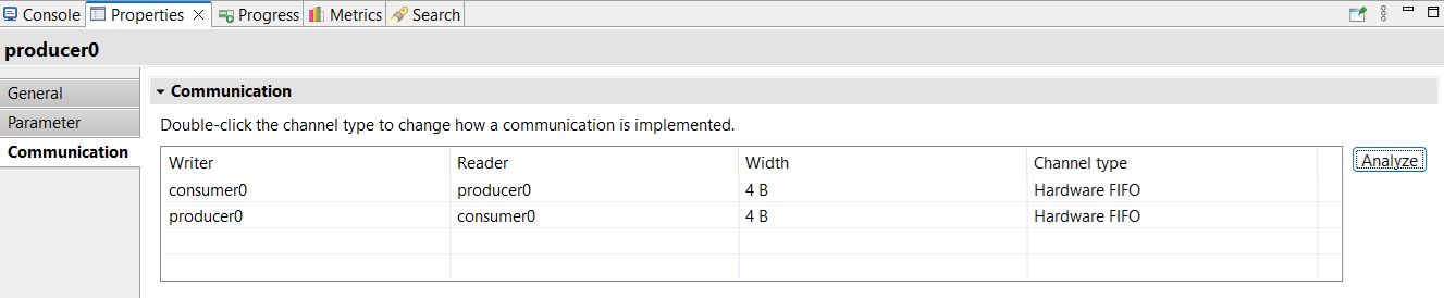
Figure 3.2 Communication tab#
Select the module from the diagram
In the Properties view, select the Communication tab
Select the desired communication type
Double-click on the Channel type cell to change it
Note
By default, the channel type for a ModuleRead/ModuleWrite communication is Hardware FIFO.
3.3.1.4. Communication architecture#
As mentioned above, a module can be mapped either as a hardware component or as a software task running on a processor. Depending on modules’ mapping, the platform architecture will change to support FIFO-based communications between modules. SpaceStudio detects the designer mapping choice and adds all required adapters and FIFOs to the hardware platform.
3.3.1.4.1. Software-software communication via hardware FIFO#
A hardware FIFO is instantiated and connected to the interconnect using an adapter. All messages passing is done through the interconnect. The figure below illustrates SW module 1 writes to SW module 2.
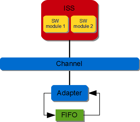
Figure 3.3 SW/SW FIFO-based communication (via hardware FIFO)#
3.3.1.4.2. Software-software communication via software FIFO#
A software FIFO is created in the data memory of the ISS. SW module 1 writes to SW module 2.
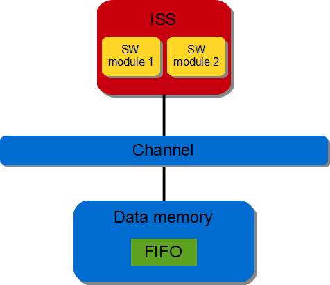
Figure 3.4 SW/SW FIFO-based communication (via software FIFO)#
3.3.1.4.3. Software-hardware communication#
A hardware FIFO is instantiated. The FIFO is directly connected to the hardware module and connected to the interconnect using an adapter. All read/write requests coming from the software module passes through the interconnect. For a software module sending messages to a hardware module through a FIFO-based operation, SpaceStudio would generate a hardware platform as the figure below.
Figure 3.5 SW/HW FIFO-based communication#
3.3.1.4.4. Hardware-hardware communication via FIFO#
A hardware FIFO is instantiated and directly connected to both hardware modules. The figure below illustrates HW module1 is writing to HW module2.
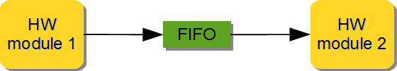
Figure 3.6 HW/HW FIFO-based communication#
3.3.1.4.5. Hardware-hardware communication via direct-streaming#
Both hardware modules are directly connected. This allows two modules to directly send data with no data buffering between them (aside from the single-element buffer described below), and with no concept of data address. It may be used with placeholder data to perform a bilateral rendezvous.
Due to the possibility of deadlocks and the definition of the underlying AXI4-Stream standard, a single-element buffer may be added between the writing and reading modules when the ModuleWrite call is non-blocking [1].
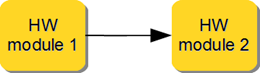
Figure 3.7 HW/HW direct-streaming communication#
3.3.2. DMA-based communications#
3.3.2.1. Principle#
Inter-module communication can also be performed using Direct Memory Access (DMA). Such communication uses the same API as for FIFO-based (ModuleRead and ModuleWrite) and are available when, for a given pair of communication, one module is mapped in hardware and the other one is mapped as software. The software module must be mapped to a processor for which, the data memory is available to the system. For example, for the microblaze, the data memory is private to the microblaze so DMA operation using the ModuleRead/ModuleWrite is not possible. However, for the Zynq, the data memory is available to the system so DMA operation using the ModuleRead/ModuleWrite is possible.
DMA operation moves data between a software module’s memory and a hardware module’s stream interface. A DMA is used for high throughput transfer of data from memory to stream and from stream to memory. SpaceStudio detects the designer mapping choice, adds all required adapters and handles all components connection.
3.3.2.2. API#
DMA-based communications are implemented with the ModuleRead and ModuleWrite function calls.
1eSpaceStatus ModuleWrite(unsigned int destination_id, uint32_t timeout)
2eSpaceStatus ModuleWrite(unsigned int destination_id, uint32_t timeout, const T& data)
3eSpaceStatus ModuleWrite(unsigned int destination_id, uint32_t timeout, const T* data, uint32_t nb_elements = 1)
1eSpaceStatus ModuleRead(unsigned int destination_id, uint32_t timeout)
2eSpaceStatus ModuleRead(unsigned int destination_id, uint32_t timeout, T& data)
3eSpaceStatus ModuleRead(unsigned int destination_id, uint32_t timeout, T* data, uint32_t nb_elements = 1)
3.3.2.2.1. Parameters#
destination_idTo facilitate communications, each module is given an identification number (id) tag which is kept valid throughout the simulation. Ids are defined in the
platform_definitions.hfile.
timeoutEvery DMA-based write or read operation can either be blocking (
SPACE_BLOCKING) or non-blocking (SPACE_NON_BLOCKING).A blocking write operation of a software module memory will block until all the data from the memory has been sent to the destination module. A non-blocking write operation immediately returns after the DMA has been configured to execute the data transfer; if the DMA configuration fails, an error code is returned. A blocking read will wait until the software module’s memory contains the data read from a predetermined source module. A non-blocking read operation immediately returns after the DMA has been configured to execute the data transfer; if the DMA configuration fails, an error code is returned.
A blocking write operation from a hardware module will block until the message is received by the DMA. A non-blocking write operation returns immediately if the DMA is not ready. Non-blocking read operations returns immediately if the DMA is not ready. Finally, a blocking read operation will wait until the requested message from a predetermined source module is received in the buffer.
dataMessage to be read/written
nb_elementsNumber of elements to be read/written (for array type message)
3.3.2.2.2. Return value#
eSpaceStatus which might be:
SPACE_OK: DMA transfer is completed (blocking) or, DMA is processing the transfer (non-blocking).SPACE_ERROR: DMA is busy
3.3.2.2.3. Example#
Please refer to section Example for FIFO-based communications for examples.
3.3.2.3. Manage communication#
ModuleRead and ModuleWrite can be performed using asynchronous message passing (hardware or software FIFO) and/or Direct Memory Access (DMA) (Please refer to section “DMA-based communications” for more information). System designers configure inter-module communication type as follows:
Select the module from the diagram
In the Properties view, select the Communication tab
Select the desired communication type
Double-click on the Channel type cell to change it
By default, the channel type for a ModuleRead/ModuleWrite communication is Hardware FIFO.
3.3.2.4. Communication architecture#
Depending on modules’ mapping, the platform architecture will change to support DMA-based communications between modules. SpaceStudio detects the designer mapping choice and adds all required adapters and DMAs to the hardware platform. For every DMA-based write/read operation a dedicated DMA channel is used.
3.3.2.4.1. Memory to stream (MM2S) communication#
A DMA directly connected to the hardware module via the DMA stream interface. The DMA data movement is done through the MM2S channel. The DMA Read Master interface is connected to an interconnect and DMA MM2S stream interface is connected to the hardware module. DMA initialization, status and management registers are accessed through a slave interface. The figure below illustrates SW module writing to HW module.
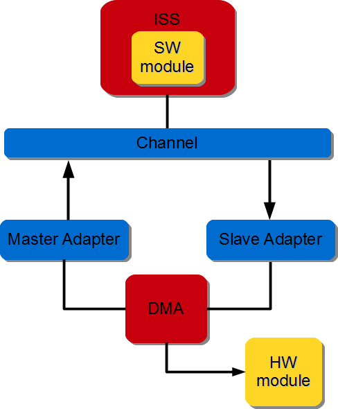
Figure 3.8 SW/HW DMA-based communication#
3.3.2.4.2. Stream to memory (S2MM) communication#
A hardware DMA and a FIFO buffer are instantiated. The FIFO is directly connected to the hardware module and to the DMA stream interface. The DMA data movement is done through the S2MM channel. The Write Master interface is connected to an interconnect and the S2MM stream interface is connected to the FIFO. The DMA initialization, status and management registers are accessed through a slave interface. The figure below illustrates HW module writing to SW module.
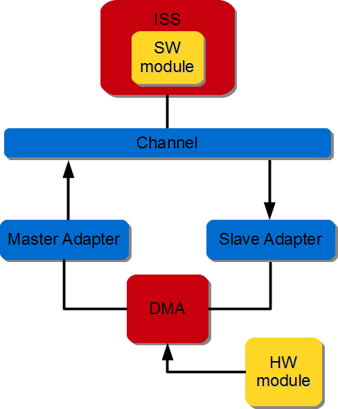
Figure 3.9 HW/SW DMA-based communication#
3.3.3. Register-based communications#
3.3.3.1. Principle#
Inter-module register-based communications are performed by writing and reading into registers shared by the modules. In other words, the source module explicitly writes data into the shared register whereas the destination module explicitly reads data from the same register. These two operations do not need to be performed simultaneously, as such a shared register stores the last value written to it and returns this value when read. Such a register can be read and written by one or several modules. Any given module can read or write several such registers.
These communications are always non-blocking, and therefore no mode parameter is present in the function prototype.
3.3.3.2. API#
Register-based communications are implemented with the RegisterRead and RegisterWrite function calls.
1eSpaceStatus RegisterWrite(unsigned int register_file_id, uint32_t register_id, const T* data)
2eSpaceStatus RegisterWrite(unsigned int register_file_id, uint32_t register_id, const T& data)
1eSpaceStatus RegisterRead(unsigned int register_file_id, uint32_t register_id, T* data)
2eSpaceStatus RegisterRead(unsigned int register_file_id, uint32_t register_id, T& data)
3.3.3.2.1. Parameters#
register_file_idTo facilitate communications, registers are grouped into register files, which are implemented by SpaceLib’s
register_filecomponent. To use register-based communications, at least oneregister_filemust be present in the simulated architecture. Severalregister_filecan be added to the simulated architecture, if necessary. SpaceStudio automatically handlesregister_fileconnections.Each register file is given an identification number (id) tag which is kept valid throughout the simulation. Ids are defined in the
platform_definitions.hfile.A register file holds a total of 1024 registers starting with the first register at 0.
register_idRegisters can be a value between 0 and 1023. We strongly encourage designer to use the
application_definitions.hfile to define application-specific register definitions. For instance:1// Filename : application_definitions.h 2#ifndef APPLICATION_DEFINITIONS_H 3#define APPLICATION_DEFINITIONS_H 4 5// ... 6 7#define WIDTH_REGISTER 0 8#define HEIGHT_REGISTER 1 9 10// ... 11 12#endif
dataData to be read/written
3.3.3.2.2. Return value#
eSpaceStatus which might be { SPACE_OK, SPACE_ERROR }.
3.3.3.2.3. Example#
- Literal
1void producer::thread() {
2   // ...
3   RegisterWrite(REGISTER_FILE0_ID, WIDTH_REGISTER, 1920);
4   // ...
5}
- Scalar
1void producer::thread() {
2   // ...
3   uint32_t width = 1920;
4   RegisterWrite(REGISTER_FILE0_ID, WIDTH_REGISTER, width);
5   // ...
6}
3.3.3.3. Communication architecture#
Depending on modules’ mapping, the platform architecture will change to support register-based communications between modules. SpaceStudio detects the designer mapping choice and adds all required adapters to the hardware platform.
3.3.3.3.1. Software-software communication#
All messaging passing is done through the interconnect. Note the designer must add a register file to architecture.
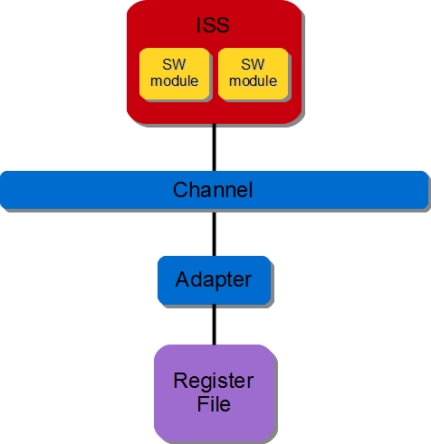
Figure 3.10 SW/SW Register-based communication#
3.3.3.3.2. Software-hardware communication#
The register file is directly connected to the hardware module. All read/write requests coming from the software module passes through the interconnect. Note the designer must add a register file to the architecture.
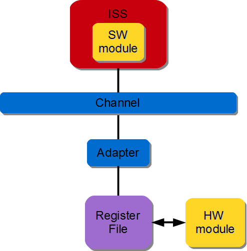
Figure 3.11 SW/HW Register-based communication#
3.3.3.3.3. Hardware-hardware communication#
The register file is directly connected to both hardware modules. Note the designer must add a register file to the architecture.
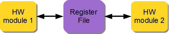
Figure 3.12 HW/HW Register-based communication#
3.4. Device communications#
3.4.1. Principle#
Modules and master devices can communicate with devices (e.g., memories, timers or peripherals). These communications are always non-blocking, and therefore no parameter to indicate a blocking or non-blocking requirement is present in the function prototype.
Because every device is also identified with an id, they are reachable using this id. Since devices are often described with internal registers or with several internal accessible addresses, an address offset parameter is supplied for such accesses.
3.4.2. API#
Device communications are implemented with the DeviceRead and DeviceWrite API.
1eSpaceStatus DeviceWrite(unsigned int destination_id, uintptr_t offset, const T* data, uint32_t nb_elements = 1)
2eSpaceStatus DeviceWrite(unsigned int destination_id, uintptr_t offset, const T& data)
1eSpaceStatus DeviceRead(unsigned int destination_id, uintptr_t offset, T* data, uint32_t nb_elements = 1)
2eSpaceStatus DeviceRead(unsigned int destination_id, uintptr_t offset, T& data)
3.4.2.1. Parameters#
destination_idTo facilitate communications, each device is given an identification number (id) tag which is kept valid throughout the simulation. Ids are defined in the
platform_definitions.hfile.
offsetOffset to be addressed (does not include the base address of the destination slave device).
dataMessage to be read/written
nb_elementsNumber of elements to be read/written (for array type message). Default is 1.
3.4.2.2. Return value#
eSpaceStatus which might be { SPACE_OK, SPACE_ERROR }.
3.4.2.3. Example#
- Array
1void producer::thread() {
2   // ...
3   uint32_t data[5] = { 1, 2, 3, 4, 5 };
4   DeviceWrite(BRAM0_ID, 0, data, 5);
5   // ...
6}
- Scalar
1void producer::thread() {
2   // ...
3   uint32_t value = 255;
4   DeviceWrite(BRAM0_ID, 0, value);
5   // ...
6}
- Literal
1void producer::thread() {
2   // ...
3   DeviceWrite(BRAM0_ID, 0, 255);
4   // ...
5}
Technical close-up
To ensure that communications work properly both in hardware and embedded software implementations, the length of the data transferred in a DeviceRead or DeviceWrite operation must be a multiple of 4 bytes. It is strongly recommended that the message buffer be aligned on a 4-byte address when the module is mapped into software: the SPACE_ALIGNED qualifier can be added to a variable declaration to ensure this.
3.4.3. Communication architecture#
3.4.3.1. Software module#
The software modules will be indirectly connected to the interconnect through a processor and all read/write requests are handled by the interconnect.
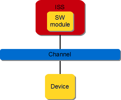
Figure 3.13 Device communication from software module#
3.4.3.2. Hardware module#
The hardware module will be directly connected to the interconnect. Again, all read/write requests are handled by the interconnect.
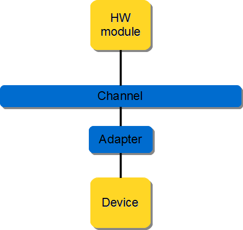
Figure 3.14 Device communication from hardware module#
3.5. Memory transfer#
SpaceLib defines a memory transfer API which allows designers to transfer data using a Direct Memory Access (DMA) or a Central Direct Memory Access (CDMA) hardware component. The DMA provides high-bandwidth direct memory access between a memory and a hardware module’s stream interface. The CDMA provides high-bandwidth direct memory access between a memory-mapped source address and memory-mapped destination address.
3.5.1. Principle#
The memory transfer API defines three data transfer operations Memory2Stream, Stream2Memory and Memory2Memory. This API requires a software controller module which must explicitly call the memory transfer API to initialize and configure the DMA.
3.5.2. API#
Memory transfer communications are implemented with the Memory2Stream, Stream2Memory and Memory2Memory API.
eSpaceStatus Memory2Stream(unsigned int memory_source_id, uintptr_t memory_source_offset, unsigned int module_destination_id, uint32_t timeout, uint32_t nb_bytes)
Memory2Stream transfers bytes from a memory specific location to a hardware module stream interface. The software module performs the Memory2Stream call while the hardware module performs a ModuleRead call to read from the stream interface.
eSpaceStatus Stream2Memory(unsigned int module_source_id, unsigned int memory_destination_id, uintptr_t memory_destination_offset, uint32_t timeout, uint32_t nb_bytes)
Stream2Memory transfers bytes from a hardware module stream interface to a memory specific location. The software module performs the Stream2Memory call while the hardware module performs a ModuleWrite call to write into the stream interface.
eSpaceStatus Memory2Memory(unsigned int memory_source_id, uintptr_t memory_source_offset, unsigned int memory_destination_id, uintptr_t memory_destination_offset, uint32_t timeout, uint32_t nb_bytes)
Memory2Memory transfers bytes from a memory specific location to another memory. The software module performs the Memory2Memory call.
3.5.2.1. Parameters#
memory_source_id/memory_destination_id/module_source_id/module_destination_idTo facilitate communications, modules and devices are given an identification number (id) tag which is kept valid throughout the simulation. Ids are defined in the
platform_definitions.hfile.
memory_source_offset/memory_destination_offsetOffset to be addressed (does not include the base address of the destination slave device).
timeoutMemory transfer can either be:
Blocking (
SPACE_BLOCKING) : block until all the data is transferredNon-blocking (
SPACE_NON_BLOCKING) : returns immediately. The return value must be checked to determine if the DMA is processing the transfer or not.
nb_bytesNumber of bytes to be transferred.
3.5.2.2. Return value#
eSpaceStatus which might be:
SPACE_OK: DMA transfer is completed (blocking) or, DMA is processing the transfer (non-blocking).SPACE_ERROR: DMA is busy
3.5.2.3. Example#
In this example, we are transferring 1024 bytes of data from the memory BRAM0_ID (at offset 0) to a hardware module. To realize this communication, the software module (controller) performs the Memory2Stream call whereas the hardware module (reader) performs the ModuleRead call.
The controller module performs a blocking memory transfer from memory device BRAM0_ID targeting the reading module, and the reading module performs the corresponding read operation from the stream interface.
1void controller::thread() {
2   // ...
3   Memory2Stream(BRAM0_ID, 0, READER0_ID, SPACE_BLOCKING, 1024);
4   // ...
5}
1void reader::thread() {
2   // ...
3   uint8_t data[1024];
4   eSpaceStatus status = ModuleRead(CONTROLLER0_ID, SPACE_NON_BLOCKING, data, 1024);
5   if (status == SPACE_OK) {
6      // valid data
7   }
8   // ...
9}
Technical close-up
To ensure that communications work properly both in hardware and embedded software implementations, it is strongly recommended that the length of the data transferred with Memory2Stream, Stream2Memory or Memory2Memory operations be a multiple of 4 bytes. This is the case in this example, where the data length is 1024 bytes. It is also strongly recommended that the length of the data transferred in a ModuleRead or ModuleWrite operation be a multiple of 4 bytes (1024x uint8_t of 1 byte each).
3.5.3. Communication architecture#
3.5.3.1. Memory to stream transfer#
A DMA and corresponding adapters are instantiated. The hardware module is directly connected to the DMA stream interface. The DMA data movement is done through the MM2S channel. The DMA Read Master interface is connected to an interconnect and DMA MM2S stream interface is connected to the hardware module. The software module (controller) performs DMA initialization, status and management registers through a slave interface which is connected to the interconnect. The figure below illustrates SW controller module ordering the DMA to stream data from memory to HW module.
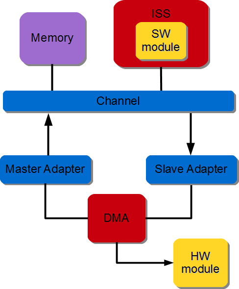
Figure 3.15 Memory to Stream data transfer#
3.5.3.2. Stream to memory transfer#
A DMA and corresponding adapters are instantiated. The hardware module is directly connected to the DMA stream interface. The DMA data movement is done through the S2MM channel. The DMA Write Master interface is connected to an interconnect and DMA S2MM stream interface is connected to the hardware module. The software module (controllers) performs DMA initialization, status and management registers through a slave interface which is connected to the interconnect. The figure below illustrates the SW controller module ordering the DMA to stream data from HW module to memory.

Figure 3.16 Stream to Memory data transfer#
3.5.3.3. Memory to memory transfer#
A DMA is instantiated and its read interface is connected to the source memory interconnect and its write interface is connected to the destination memory interconnect. The software module (controller) performs DMA initialization, status and management registers through a slave interface. The figure below illustrates the SW controller ordering the DMA to transfer data between two memories.
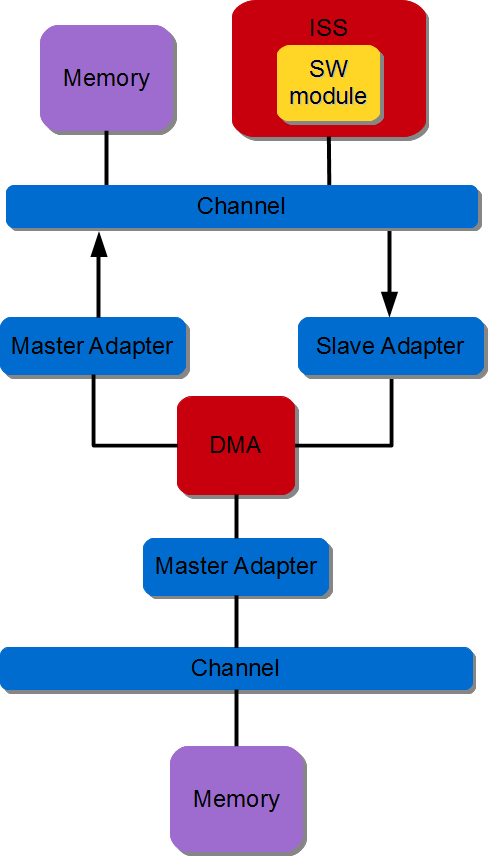
Figure 3.17 Memory to Memory data transfer#
Footnotes
3.6. Clock counters#
3.6.1. Principle#
The Clkctr API provides a unified mechanism for retrieving the current time in both software modules and HLS-generated hardware modules. When used in hardware, the API generates a dedicated hardware counter IP. When used in software, it retrieves the system time through the operating system, in a manner similar to the std::chrono library.
The Clkctr API is based on the concept of clock domains. This concept is extended to software environments: a clock domain may correspond either to a physical hardware clock or to an operating system instance. Each OS is treated as an independent clock domain. Because each domain maintains its own time base, the user must specify the target clock domain when using a Clkctr.
The API currently supports the following use cases:
A software module retrieving the time of a software module (including itself).
A software module retrieving the time of a hardware module.
A hardware module retrieving its own time.
3.6.2. API#
The Clkctr API is declared in the space_chrono.h header. It is accessed through a clock_handle object, which is created using the SPACE_CLKCTR_HANDLE macro.
A clock_handle object is specific to the pair composed of the calling thread and the target clock domain. This association uniquely identifies a time access path within the application, which is required by SpaceStudio to perform static analysis of the application architecture.
The type of a specific clock_handle can be obtained with the SPACE_CLKCTR_HANDLE_T macro, although using decltype() or auto is generally preferred.
3.6.2.1. Macros#
- SPACE_CLKCTR_HANDLE(calling_module, calling_idx, calling_thread, SPACE_ID(target_module, target_idx), clk_variable)
This macro instantiates a
clock_handleinstance set up to read a selected clock domain from a given module thread.- Parameters:
calling_module – Name of the module calling the macro.
calling_idx – Index of the module calling the macro.
calling_thread – Name of the thread method calling the macro.
target_module – Name of the module whose clock domain is read by the clock handle.
target_idx – Index of the module whose clock domain is read by the clock handle.
clk_variable – Name of the variable that will store the clock_handle object.
- SPACE_CLKCTR_HANDLE_T(calling_module, calling_idx, calling_thread, SPACE_ID(target_module, target_idx))
This macro expands to the type of a
clock_handleassociated with the specified caller thread and target clock domain. It is equivalent to usingdecltype(clk_variable)if the correspondingclock_handlehas already been instantiated.- Parameters:
calling_module – Name of the module calling the macro.
calling_idx – Index of the module calling the macro.
calling_thread – Name of the thread method calling the macro.
target_module – Name of the module whose clock domain is read by the clock handle.
target_idx – Index of the module whose clock domain is read by the clock handle.
3.6.2.2. clock_handle class#
3.6.2.2.1. Member types#
-
type rep#
The rep type is defined as a uint64_t. It’s the type used by the internal counter of a
clock_handle.typedef uint64_t rep;
3.6.2.2.2. Functions#
-
time now()#
- Returns:
A
timeobject representing the current time of the associated clock, measured as the number of ticks or cycles elapsed since the epoch. Thetimeclass is specific to theclock_handleused to call the method.
3.6.2.3. time class#
The clock_handle class contains a nested time class that defines the representation and operations of a time point. Each clock_handle instance created through the associated macro defines its own time type, which is specific to the target clock domain and calling module thread.
3.6.2.3.1. Functions#
-
rep jiffies()#
- Returns:
The internal counter value of the
timeobject. It represents a number of clock cycles if the target clock domain is in hardware, or a number of OS ticks if the target clock domain is an operating system.
-
template<>
Type to_sec<Type>()# - Template Parameters:
Type – Numeric type used for the return value (e.g., float, double).
- Returns:
The value of the
timeobject in seconds, represented as the specified type. This method is currently only available for software clock domains.
3.6.2.3.2. Static functions#
-
static time from_jiffies(rep jiffies)#
- Param:
jiffies: Counter value used to initialize the
timeobject.- Returns:
A new
timeobject initialized with the specified counter value.
-
static time zero()#
- Returns:
A
timeobject initialized with a counter value of 0, corresponding to the epoch. This method is rarely used directly, since the API is mainly designed to track the time elapsed between two points.
3.6.2.3.3. Operators#
Objects of the same time class support arithmetic and comparison operators:
Arithmetic operators:
+,+=,-,-=.Comparison operators:
>,<,==,!=,<=,>=.
These operators allow the user to perform time calculations and comparisons directly between time objects.
3.6.3. Example#
The Clkctr API is primarily used to measure the elapsed time between two time points. The following example demonstrates its usage:
#include "space_chrono.h"

// ...

void producer::thread(SPACECOMP_THREAD_PARAMS(producer, INDEX, thread)) {
    spacecomp_thread_initialize();

    // Create a clock_handle 'consclk' tracking the clock domain of the consumer
    // module from this producer module
    SPACE_CLKCTR_HANDLE(producer, INDEX, thread, SPACE_ID(consumer, INDEX), consclk);

    // Type alias for the consclk clock handle
    typedef SPACE_CLKCTR_HANDLE_T(producer, INDEX, thread, SPACE_ID(consumer, INDEX)) consclk_t;

    // Record start time
    consclk_t::time start = consclk.now();

    // ... code to measure ...

    // Record end time
    consclk_t::time end = consclk.now();

    // Compute elapsed time
    consclk_t::time elapsed = end - start;

#if CONSUMER_SW  // Software target domain
    float elapsed_sec = elapsed.to_sec<float>();

#else  // Hardware target domain
    uint32_t hw_frequency = 100e6;
    consclk_t::rep elapsed_ticks = elapsed.jiffies();
    float elapsed_sec = static_cast<float>(elapsed_ticks) / static_cast<float>(hw_frequency);
#endif
}
The use of decltype() or auto is recommended to prevent type mistakes and improve readability. The SPACE_CLKCTR_HANDLE_T macro should be reserved to cases where C++11 is not available, and decltype() or auto not defined.
3.7. Time monitors#
3.7.1. Principle#
Time monitors, referred to as timemons, provide a mechanism to monitor timing data during application execution. Timemons are internally based on Clkctrs and operate uniformly across both hardware and software clock domains.
A timemon is accessed through a timemon_handle object, which is instantiated using the SPACE_TIMEMON_HANDLE macro. Unlike Clkctrs, a timemon can only refer to its own clock domain, which is implicitly determined by the calling thread of the timemon_handle.
Once instantiated, a timemon is controlled using the start(), pause(), and stop() methods. A timemon measures the time between each start() and stop() call, referred to as a measurement cycle. The pause() method suspends the current measurement cycle without terminating it. A subsequent call to start() resumes the same cycle until stop() is called. For each timemon, the following statistics are maintained:
Minimum measurement cycle duration
Maximum measurement cycle duration
Total accumulated time across all cycles
Number of measurement cycles
The API also provides RAII guard class templates. An instance of active_guard starts or resumes the associated timemon upon construction and stops it upon destruction. Oppositely, an instance of inactive_guard pauses the timemon upon construction and resumes it upon destruction. Using these guards within a block scope ensures automatic control of the timemon lifecycle.
Multiple timemons may exist within the same clock domain to monitor different parts of the execution. Each timemon is assigned a category index, chosen by the user, and a label, used to identify the monitor in the output results. Category indexes must be unique across all clock domains, and all handles referring to the same category must use the same label.
Multiple timemon_handle objects from different component instances may refer to the same timemon using the same category index, provided that all instances are within the same clock domain. Control methods invoked from any of those handles affect the same measurement, this allows monitoring execution that spans multiple components. For example, a timemon can measure the time from the start of a write operation in a producer module to the end of a read operation in a consumer module, with handles in both modules referring to the same category index.
A timemon handle also takes an enabled flag, which allows enabling or disabling a monitor without heavy code modification. Disabled timemons have no impact on application execution.
At the end of execution, the statistics collected for each timemon are sent to the standard output, identified by their category label.
Note
The timemon API is still under development. The output format of timemons is subject to change in the future.
3.7.2. API#
3.7.2.1. Macros#
-
SPACE_TIMEMON_HANDLE(calling_module, calling_idx, calling_thread, category_idx, enabled, timemon_variable, timemon_label)#
This macro instantiates a
timemon_handleobject, providing access to a specific timemon within a clock domain. A timemon handle is associated with a calling thread, a user-defined category, a label, and an enabled flag.- Parameters:
calling_module – Name of the module calling the macro.
calling_idx – Index of the module calling the macro.
calling_thread – Name of the thread method calling the macro.
category_idx – User-defined integer representing the timemon category.
enabled – Boolean flag (true to enable, false to disable).
timemon_variable – Name of the variable that will store the
timemon_handleobject.timemon_label – Label given to the timemon category, used in output.
-
SPACE_TIMEMON_HANDLE_T(calling_module, calling_idx, calling_thread, category_idx, enabled)#
This macro expands to the type of a
clock_handleassociated with the specified caller thread and target clock domain. It is equivalent to usingdecltype(clk_variable)if the correspondingclock_handlehas already been instantiated.- Parameters:
calling_module – Name of the module calling the macro.
calling_idx – Index of the module calling the macro.
calling_thread – Name of the thread method calling the macro.
category_idx – User-defined integer representing the timemon category.
enabled – Boolean flag (true to enable, false to disable).
3.7.2.2. timemon_handle class#
3.7.2.2.1. Functions#
-
void start()#
Starts a new measurement cycle for the associated timemon or resumes a cycle that was previously paused.
-
void pause()#
Pauses the current measurement cycle for the associated timemon without ending it. The cycle can be resumed later by calling
start().
-
void stop()#
Stops the current measurement cycle, computes its duration and updates the associated timemon values (min, max, total, count).
3.7.2.3. RAII Guards#
The timemon API provides RAII-style guard class templates to automate timemon control within a scope. Both active_guard and inactive_guard are class templates, with a template parameter specifying the type of the associated timemon_handle. The templates are defined in the space::chrono::perf namespace.
A guard object is constructed with a timemon_handle instance of the corresponding type. The guard then automatically manages the measurement cycle for the lifetime of the object.
The template type should use the decltype specifier. For pre-C++11 environments, the SPACE_TIMEMON_HANDLE_T macro can be used instead.
3.7.2.3.1. Active guard#
An active_guard object calls start() on creation and stop() on destruction, on the associated timemon.
Usage:
// Execution part not monitored by the timemon
// ...
{
    using namespace space::chrono::perf;

    // An active guard "ag" managing the "timemon_handle" object.
    // The guard is automatically destroyed at the end of the scope block.
    active_guard<decltype(timemon_handle)> ag{timemon_handle};

    // Execution part to monitor
    // ...
}

// Execution part not monitored by the timemon
// ...
3.7.2.3.2. Inactive guard#
An inactive_guard object calls pause() on creation and start() on destruction, on the associated timemon.
Usage:
timemon_handle.start();

// Execution part monitored by the timemon
// ...

{
    using namespace space::chrono::perf;

    // An inactive guard "ig" managing the "timemon_handle" object.
    // The guard is automatically destroyed at the end of the scope block.
    inactive_guard<decltype(timemon_handle)> ig{timemon_handle};

    // Execution part to exclude from monitoring
    // ...
}

// Execution part monitored by the timemon resumes
// ...

timemon_handle.stop();
3.7.2.4. Timemon results#
At the end of execution, the recorded values of each timemon are formatted and sent to the standard output. The following values are reported:
CATEGORY: The timemon category, identified by its label.
MIN: The minimum duration of a measurement cycle for the category.
MAX: The maximum duration of a measurement cycle for the category.
COUNT: Number of measurement cycles executed.
TOTAL: Accumulated duration of all measurement cycles.
The MIN, MAX, and TOTAL values are expressed in clock cycles for hardware domains or OS ticks for software domains, similar to the value returned by the jiffies() method of a Clkctr.
For example, the output of the timemons for a purely hardware producer-consumer architecture is as follows:
CATEGORY      | MIN        | MAX        | COUNT | TOTAL
------------- |------------|------------|-------|--------------
Produce data  | 4132864558 | 5286642874 |    50 | 239332422709
Transfer data |   90756642 |   95254648 |    50 |   4624281150
Consume data  |  135476118 |  173324856 |    50 |   7187737758
3.7.3. Example#
The following example illustrates the use of timemons in a producer-consumer application. Three timemons are defined to monitor distinct parts of the execution:
Data production in the producer
Data transfer between producer and consumer
Data consumption in the consumer
The transfer timemon is shared between both components using the same category index, allowing measurement of the time between the start of the write operation and the completion of the corresponding read. This configuration is only valid if the producer and consumer modules share the same clock domain.
An activation flag is defined in application_definitions.h to enable or disable monitoring easily.
// application_definitions.h

//...

#define ENABLE_MONITORING true
// producer.cpp

#include "space_chrono.h"

// ...

void producer::thread(SPACECOMP_THREAD_PARAMS(producer, INDEX, thread)) {
    spacecomp_thread_initialize();

    SPACE_TIMEMON_HANDLE(producer, INDEX, thread, 0, ENABLE_MONITORING, prod_mon, "Produce data");

    SPACE_TIMEMON_HANDLE(producer, INDEX, thread, 1, ENABLE_MONITORING, transfer_mon, "Transfer data");

    while(1){
        spacecomp_thread_loop_start();

        {
            active_guard<decltype(prod_mon)> produce_guard{prod_mon};

            // Code to produce data
            // ...
        }

        transfer_mon.start();

        // Code to send data to consumer
        // ...
    }
}
// consumer.cpp

#include "space_chrono.h"

// ...

void consume::thread(SPACECOMP_THREAD_PARAMS(consumer, INDEX, thread)) {
    spacecomp_thread_initialize();

    SPACE_TIMEMON_HANDLE(consumer, INDEX, thread, 2, ENABLE_MONITORING, cons_mon, "Consume data");

    SPACE_TIMEMON_HANDLE(consumer, INDEX, thread, 1, ENABLE_MONITORING, transfer_mon, "Transfer data");

    while(1){
        spacecomp_thread_loop_start();

        // Code to receive data from producer
        // ...

        transfer_mon.stop();

        {
            active_guard<decltype(cons_mon)> consume_guard{cons_mon};

            // Code to consume data
            // ...
        }
    }
}