6. Implementing Hardware Component#
6.1. Introduction#
SpaceStudio transforms executable high-level specifications of system functionality and architecture into concrete hardware and software implementations deployable on FPGA platforms. This transformation is performed through the Architecture Implementation workflow within the SpaceStudio environment. This document explains how users—either manually or through automated synthesis processes—define and implement modules and devices mapped to hardware fabric during the Architecture Implementation phase.
Note
In many ways, this document is complementary to Architecture Implementation documentation and does not repeat its content.
- There are two approaches for defining hardware implementations of module and device components:
Automated HLS Synthesis: Using behavioral High-Level Synthesis (HLS) tools to automatically translate C/C++ algorithmic descriptions into synthesizable RTL (Register Transfer Level) implementations. This workflow is described in High-Level Synthesis (HLS).
Manual HDL Implementation: Directly providing hand-coded RTL implementations in Hardware Description Languages (VHDL or Verilog). This approach is described in Manual Instance Implementation and is currently the only supported implementation method for device components, which require precise control over hardware interfaces and timing.
Note
Software-mapped modules are automatically compiled using standard embedded toolchains (GCC cross-compilers, vendor-specific compilers) during Architecture Implementation. The compilation process for software modules is handled transparently by SpaceStudio and does not require the hardware implementation strategies described in this document.
6.2. High-Level Synthesis (HLS)#
High-Level Synthesis (HLS) tools automatically transform algorithmic C/C++ descriptions of module behavior into synthesizable RTL hardware implementations (Verilog/VHDL), which are then integrated into the FPGA design flow. This section explains HLS tool integration within SpaceStudio and provides guidelines on synthesizable C/C++ language constructs and coding practices.
6.2.1. Supported HLS tools#
SpaceStudio supports the following High-Level Synthesis (HLS) tools:
Vitis HLS 2025.2
Siemens Catapult HLS 2022.2
6.2.2. Enabling and Configuring#
HLS tools are configured through SpaceStudio’s preferences interface. Before enabling an HLS tool, verify that you have installed a SpaceStudio-supported version and that the installation path is accessible. To enable and configure an HLS tool:
Click the Tools menu
From the submenu, select Preferences…
In the left navigation pane, expand the hierarchy: SpaceStudio → EDA
Select the target EDA vendor and version (e.g., Xilinx – Vivado 2025.2)
Enable both the EDA is enabled and HLS tool is enabled checkboxes, then configure the required settings including installation path, license configuration, and associated EDA tool linkage. This configuration is illustrated in Figure 6.1.
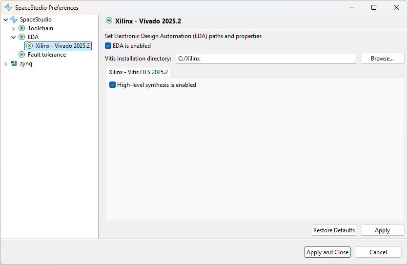
Figure 6.1 Enabling an HLS tool#
6.2.3. Invoking HLS on Instances#
To invoke HLS synthesis during the Architecture Implementation workflow, use the Architecture Implementation export configuration window that appears at the start of the implementation process. Select the hardware module instances to be synthesized by checking their corresponding checkboxes, as shown in Figure 6.2. Note that the HLS configuration section (“High-level synthesis” and “Modules instances to synthesize”) is displayed only when the architecture contains at least one module instance mapped to hardware.
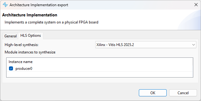
Figure 6.2 Architecture Implementation export configuration#
SpaceStudio will automatically invoke the selected HLS tool for each checked instance, perform C/C++ to RTL synthesis, generate IP packaging metadata, and integrate the resulting hardware IP blocks into the overall system design. Any synthesis errors, warnings, or optimization reports generated by the HLS tool will be displayed in SpaceStudio’s console view, allowing you to diagnose and resolve compilation issues.
6.2.4. Limitations and Guidelines of High-Level Synthesizers#
C/C++/SystemC HLS tools enable software developers to design hardware accelerators using familiar high-level programming paradigms, significantly reducing design iteration time compared to manual RTL coding. However, fundamental semantic differences exist between sequential C/C++ execution models and concurrent hardware implementations [1]. To bridge this gap, HLS tools either reject unsupported constructs with compilation errors or attempt to infer hardware structure through dataflow and control flow analysis [2].
This inference process is not always successful. Ambiguous code patterns may cause the HLS tool to fail with synthesis errors, or in some cases, silently generate functionally incorrect hardware despite the C/C++ code being logically correct in software simulation. When encountering synthesis issues, carefully review the HLS tool’s diagnostic messages (displayed in SpaceStudio’s console), which often identify problematic code patterns, provide optimization hints, or suggest alternative coding styles. While every HLS tool has its own capabilities, in general a fully synthesizable module:
Supports C/C++ primitive data types: integer types (
char,short,int,long,long long), floating-point types (float,double), boolean (bool), and enumerated types (enum)Supports fixed-size arrays of primitive and composite data types
Supports data structures (
struct) composed of primitive types or nested structures (hierarchicalstructdefinitions)Limited support for pointers: Simple pointer arithmetic and array indexing may work, but complex pointer manipulations (pointer aliasing, indirect function calls, linked data structures) are generally unsynthesizable. Avoid pointers unless necessary and keep usage patterns simple.
Limited support for standard library functions: Basic mathematical functions from
math.h(sqrt,sin,cos, etc.) may be synthesizable depending on the HLS tool’s library support. Support is tool-dependent and not guaranteed by SpaceStudio.Does not support dynamic memory allocation: Operations like
new,delete,malloc,free, andreallocare fundamentally incompatible with hardware synthesis, as they require runtime memory management.Does not support dynamic type operations: Runtime type identification and casting (
dynamic_cast,reinterpret_cast,typeid) are unsynthesizable because hardware interfaces and data paths must be statically determined at compile time.
For comprehensive HLS coding guidelines and best practices:
Vitis HLS: Vitis HLS Coding Guidelines - Covers loop optimization directives, interface protocols, dataflow pipelining, and memory optimization techniques
Siemens Catapult HLS: Catapult HLS Coding Guidelines - Provides architectural patterns, coding styles, and performance optimization strategies
SpaceStudio’s communication API enforces synthesizable coding patterns to ensure successful HLS compilation. When ambiguous or unsynthesizable constructs are detected, SpaceStudio issues diagnostic messages (warnings for potentially problematic patterns, errors for definitively unsynthesizable constructs) to guide developers toward HLS-compatible code. For example, the following error indicates that type information has been obscured by casting:
[1/1] ERROR: The data buffer argument of a DeviceRead contains a cast of an array/pointer expression.
 SpaceStudio disallows this because the communication functions need to know the true type of the array/pointer they are using.
 NOTE: Here: DeviceRead(ZYNQ_DDR0_ID, IMG_IN_IFRANGE_OFFSET, (uint32_t*)imgin, IMGSZ)
6.3. Manual Instance Implementation#
This section describes the methodology for manual hardware implementation of module or device instances by defining their communication interfaces in HDL (Hardware Description Language). Manual implementation is appropriate when:
Precise control over hardware architecture, resource utilization, or timing is required
Existing, validated hardware IP cores must be integrated into the SpaceStudio design flow
Performance-critical modules require hand-optimized RTL beyond HLS capabilities
Device peripherals with complex timing protocols or external interfaces are being developed
Component interfaces are automatically inferred from the module/device’s usage of SpaceStudio’s communication API in C/C++ code. This document focuses on the generated interface specifications and implementation requirements. For details on the C/C++ communication API itself, refer to the Introduction to System Design manual.
6.3.1. Manual Instance Implementation Workflow#
The manual hardware implementation workflow consists of the following steps:
Select manual implementation mode: Request manual implementation for specific module instances by unchecking their corresponding checkboxes in the Architecture Implementation export window (shown in Figure 6.2). Device instances always require manual implementation. To exclude a device from hardware implementation entirely (simulation-only), set its “Only used for simulation” property to true (refer to the Architecture Implementation User Guide for details).
Interface generation: SpaceStudio analyzes each manually-implemented module/device instance, infers its communication interfaces from API usage, and generates a template VHDL entity file containing the complete interface specification with properly-typed ports and detailed comments.
Implement hardware logic: Complete the implementation by writing VHDL/Verilog code that provides the functional behavior for each instance. The implementation may span multiple HDL files and can include vendor-specific IP instantiations or custom RTL modules.
Complete synthesis flow: Proceed with the Architecture Implementation process, which will integrate the manually-implemented components into the overall system design and invoke the EDA toolchain for synthesis, place-and-route, and bitstream generation.
The below sections focus on steps 2 and 3. Step 4 is the subject of the Architecture Implementation documentation.
6.3.2. Communication Interface Inference#
Communication interfaces are specified through SpaceStudio’s C/C++ communication API. Each API call in the module/device source code corresponds to a specific hardware interface type. Device components always include a slave memory-mapped interface for processor access, in addition to any interfaces requested via explicit API calls.
During the interface inference phase, SpaceStudio performs static analysis of the C/C++ source code, identifying all communication API invocations and their parameters (source/destination identifiers, data types, buffer sizes). From this analysis, SpaceStudio determines the complete set of required hardware interfaces, their types (streaming, register-based, memory-mapped), and their bit-width specifications. The interface generation rules for each communication pattern are detailed in the subsequent sections.
Table 6.1 describes which case generates which interface kind. This allows to know what interfaces to expect for a given module/device instance.
Case |
Type of generated interface |
Described in |
|---|---|---|
Call to |
Streaming |
|
Call to |
Register |
|
Call to |
Memory-Mapped (master) |
|
Device component |
Memory-Mapped (slave) |
|
Call to |
N/A [3] |
N/A |
6.3.3. Template Hardware File to Complete#
After completing interface inference for all manually-implemented instances, Architecture Implementation generates a template VHDL entity file for each instance and pauses the workflow to allow user implementation. These template files are created at the following location within the implementation directory structure:
${arch_impl_dir}/application_repository/core/${component}/src/${component}.vhd
Where:
* ${arch_impl_dir} is the root directory selected in the Architecture Implementation export window
* ${component} is the name of the component instance requiring manual implementation
Hardware IP implementations typically consist of state machines or datapaths that react to input interfaces, perform computations or transformations, and drive output interfaces. The following sections provide detailed specifications for each interface type generated by SpaceStudio.
6.3.4. Global Ports#
In addition to an instance’s communication interfaces, the signals given in Table 6.2 are always generated in the instance’s template VHDL file.
PORT NAME |
DIRECTION |
NOTES |
|---|---|---|
|
|
|
|
|
Active-high |
6.3.5. Streaming Interfaces#
Streaming interfaces are unidirectional data channels that transfer data sequentially without address information. Unlike memory-mapped interfaces, streaming communication does not use addressing—data flows continuously from producer to consumer in a point-to-point or queued fashion.
Calls to SpaceStudio’s ModuleRead/ModuleWrite API automatically generate streaming interfaces in the component’s template VHDL file. SpaceStudio supports three streaming communication topologies (detailed in the “Introduction to System Design” document):
FIFO-buffered communication: The writing module pushes data into an intermediate FIFO buffer, which is later consumed by the reading module. This decouples producer and consumer timing.
DMA transfer: A software module initiates DMA (Direct Memory Access) to stream data to/from a hardware module via dedicated DMA engine hardware.
Direct streaming: Writer and reader modules connect directly with handshaking signals, enabling zero-latency data transfer when both are ready.
SpaceStudio generates one streaming read interface per unique ModuleRead call and one streaming write interface per unique ModuleWrite call. Interfaces are differentiated by the triplet (source_id, destination_id, channel_width), where:
* channel_width specifies the data path width in bits
* For hardware-to-hardware communication, channel_width equals the data type size
* For software-hardware communication, channel_width matches the system interconnect data width (typically 32 or 64 bits)
6.3.5.1. AXI4-Stream Interface Signals#
SpaceStudio employs the industry-standard AXI4-Stream protocol for all streaming interfaces. AXI4-Stream is a widely-adopted, handshake-based streaming protocol developed by ARM, supported by most FPGA vendor IP and EDA tools.
The generated template VHDL files include the signal definitions shown in Section 6.3.6 (for streaming outputs) and Section 6.3.6 (for streaming inputs). Port names in the VHDL entity follow AXI4-Stream naming conventions prefixed with instance-specific identifiers. For complete protocol specifications, including timing diagrams and advanced features, refer to the ARM AMBA AXI4-Stream specification, “Signal List” section.
Tip
Each generated AXI4-Stream interface is preceded by a descriptive comment in the template VHDL file, identifying the communication endpoint and data type. Use these comments to understand the purpose and connectivity of each interface.
6.3.6. Register-Based Interfaces#
Calls to SpaceStudio’s RegisterRead/RegisterWrite API generate lightweight register-based interfaces in the component’s template VHDL file. Register-based communication utilizes SpaceStudio’s register_file infrastructure—a hardware register bank of 32-bit registers that provides low-latency, single-cycle access for sharing configuration parameters, status flags, and control signals between hardware modules and software tasks.
For each unique (register_file_id, register_id) pair accessed via RegisterWrite, SpaceStudio generates a dedicated write interface consisting of data and enable signals. Similarly, each unique (register_file_id, register_id) pair accessed via RegisterRead generates a corresponding read interface with a data output signal. This granular interface generation ensures minimal hardware overhead—only actually-used registers generate interface logic.
6.3.6.1. Register Read/Write Interface Signals#
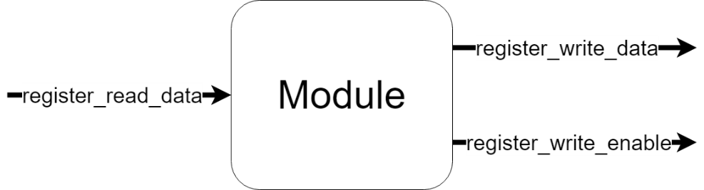
Figure 6.3 Module with one Register Read and Register Write interfaces#
Register interfaces operate with single-cycle latency: writes complete in one clock cycle, and read data is always valid (reflects the current register state). This deterministic, low-latency behavior eliminates the need for handshake protocols, simplifying the interface as shown in Section 6.3.6.1.1 and Section 6.3.6.1.1.
6.3.6.1.1. Write Operation#
Registers are implemented as 32-bit flip-flop banks (vectors of D flip-flops with synchronous write enable). Each write operation atomically replaces the entire 32-bit register contents with new data. When register_write_enable is asserted during a clock cycle, the value on register_write_data is captured on the next rising clock edge. Write operations never fail—there is no back-pressure or flow control mechanism.
Figure 6.4 represents a module with a register write interface.
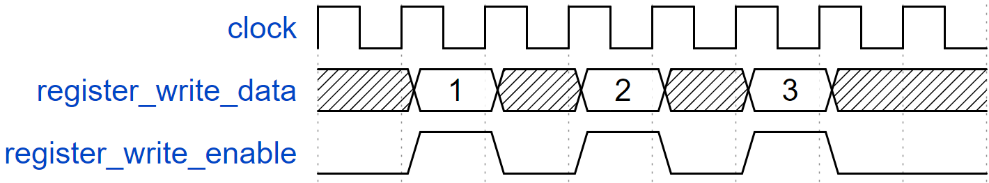
Figure 6.4 Register write operation#
6.3.6.1.2. Read Operation#
Register read interfaces provide combinational access to the register state. The register_read_data signal continuously reflects the current 32-bit register value with no latency—changes to the register are immediately visible. Read operations are always successful and never stall or fail.
Figure 6.5 represents a module with a register read interface. The value on the register_read_data signal varies in time depending on the content of that register.
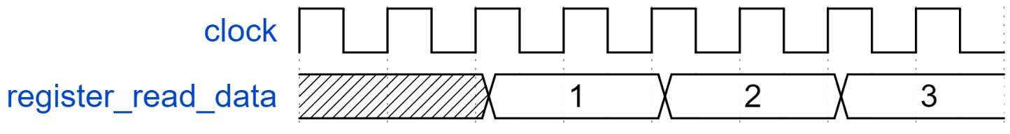
Figure 6.5 Register read operation#
6.3.7. Memory-Mapped Interfaces#
Memory-mapped interfaces implement address-based communication, where each transaction includes both a memory address/offset and associated data. This paradigm enables random access to slave devices such as DDR memory, BRAM blocks, or custom peripheral devices. The template VHDL files may contain two interface types:
Master memory-mapped interfaces: Initiate read/write transactions to slave devices
Slave memory-mapped interfaces: Respond to read/write requests from masters (processors, DMA engines, other master modules)
Calls to SpaceStudio’s DeviceRead/DeviceWrite API (available in both modules and device implementations) automatically generate master memory-mapped interfaces in the template VHDL file, establishing connections to the specified target devices. SpaceStudio optimizes interface generation:
* If a module accesses multiple devices reachable through a common interconnect, SpaceStudio generates a single shared master interface
* If devices reside on separate interconnect hierarchies, multiple independent master interfaces are generated
Device components always include exactly one slave memory-mapped interface for processor/master access. Modules never implement slave memory-mapped interfaces—for hardware-to-module communication, use register-based or streaming interfaces instead.
Important
It is strongly recommended to assign fixed address ranges to devices to ensure deterministic memory mapping during Architecture Implementation. Locking the address range guarantees that your manual HDL implementation accesses the device at the expected address, preventing address conflicts and simplifying software development.
As shown in Figure 6.6, address ranges can be locked through the SpaceStudio GUI:
Select the device instance in the architecture diagram
Navigate to the Properties view → Parameters tab
Click the lock icon next to the address range field until it shows the locked state
This procedure applies to all memory-mapped components: custom Device instances, BRAM controllers, memory controllers, and other peripheral IP blocks.
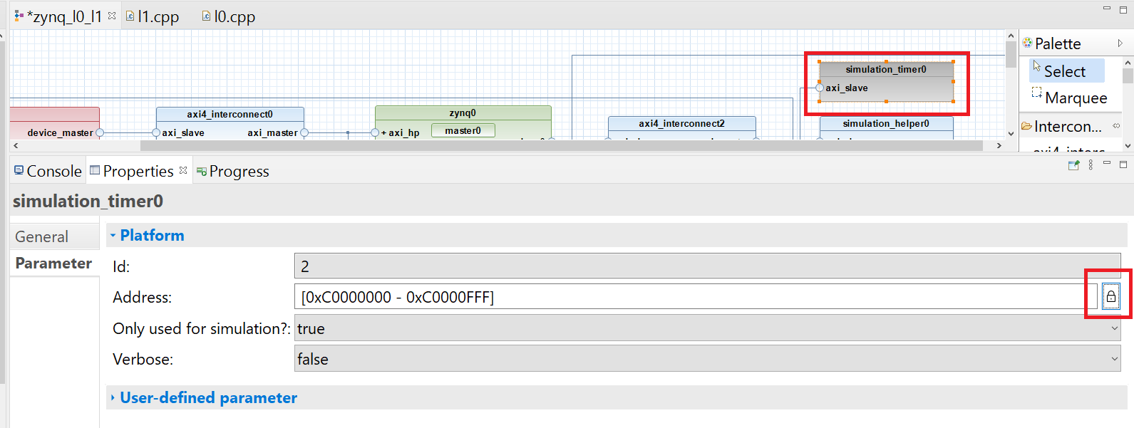
Figure 6.6 Fixing Device Address#
6.3.7.1. AXI4 Interface Signals#
The full AXI4 protocol includes numerous optional signals for advanced features (QoS arbitration, cache coherency, secure transactions, user-defined sideband data). Many of these features are unused in typical embedded FPGA systems. For simplified implementations, the signals listed in tbl_trivial_axi4_signals can be assigned fixed default values when driving master interfaces, or safely ignored when implementing slave interfaces. These default values are derived from the ARM AMBA AXI4 specification, section “A10.3 - Default signal values”, and represent the most common, non-specialized transaction types.
For example, SpaceStudio-generated systems do not utilize byte-level write strobing—all data transfers write full words. Therefore, all WSTRB (write strobe) bits should be driven HIGH (all ones), indicating that every byte lane contains valid data.
Footnotes